1 Introduction 2 Modbus communication principle Figure 1 Modbus PDU structure Table I Figure 2 Modbus PDU addressing mode Figure 3 Comparison of two ADUs 3 Modbus-TCP application 4 Conclusion Fiber Adapter,also known as bulkheads, is used to join two fiber optic patch cables together and get low insertion loss to transmission optical signal. They are available to connect either singlemode or multimode patch cables. Fiber Optic Adapter have the merits of low insertion loss, good interchangeability and reproducibility. There are various types for optical adapters,such as SC Adapter , LC Adapter, FC Adapter , ST Adapter , Fiber Hybrid Adapter. Fiber adapters are widely applied in optical communication system, cable television network, LAN&WAM, fiber optic access network and video transmission. Foclink, a reliable supplier of fiber adapter, is always beside u 7*24. Fiber Adapter Fiber Optic Adapter,Optical Adapter,SC Adapter,Fiber Hybrid Adapter Foclink Co., Ltd , https://www.scfiberpigtail.com
The Modbus application layer protocol was developed by the American Modicon company (now a brand of Schneider Electric) in 1979, and is used to realize the communication between its PLC products and the host computer. Because of its simplicity and ease of use, it has been adopted and supported by a large number of industrial automation instrumentation companies. In fact, it has become an industry standard. China ’s Standardization Committee has adopted the Modbus protocol as the industry standard for China ’s industrial automation, and has formulated GB / Z19582.1 -2004 (Modbus application layer protocol), GB / Z19582.2-2004 (Modbus on serial link) and GB / Z19582.3-2004 (Modbus-TCP) three standards. The Modbus application layer protocol is located in the seventh layer of the OSI model, and it is embedded in different low-level protocols to form three specific communication methods: Modbus serial link, Modbus-Plus and Modbus-TCP, three communication networks The device can achieve the purpose of data exchange through the gateway. Over the years, the prosperity of Ethernet has made it very necessary to embed the Modbus protocol in the TCP / IP protocol to achieve communication between Modbus devices. In view of this, Schneider Electric released the Modbus-TCP protocol in 1999, so that Modbus devices on Ethernet can Communicate via port 502.
PLC occupies a large proportion in the field of industrial automation control. The number of control points in some large-scale control systems reaches tens of thousands. Using conventional channel measurement methods to measure PLC channels often takes a lot of time and has low efficiency. This article aims at Schneider Electric's Quantum series PLC, through the introduction of Modbus-TCP protocol to achieve communication between ordinary computer and PLC, using ordinary computer to replace the programmer to conduct channel measurement test. Operators can quickly complete the channel detection without having to be familiar with the communication between PLC and computer, which improves the work efficiency.
2.1 Modbus application layer protocol
Modbus application layer protocol is located in the seventh layer of the ISO / OSI reference model. It implements client-server communication between different devices through a request-response mechanism. First, the client sends a request message to the server. After receiving the message, the server performs an error check. If the message is correct, it performs the operation and returns a response message to the client. One communication cycle. The Modbus protocol defines a message format that has nothing to do with the transport layer. The message is called a protocol data element (PDU). The protocol data element is composed of a function code occupying one byte and a data field with a maximum length of 252 bytes. The composition form is shown in Figure 1 below: 
The effective value range of function codes is 1 ~ 255, and the classification of function codes is divided into three categories: public function codes, user-defined function codes and reserved function codes. The function code in the message sent by the client to the server indicates the operation to be performed by the server, and some function codes also have sub-function codes for performing multi-step operations. If the message received by the server is correct and executed, the function code in the message returned by the server tells the client device that the information is the result of execution according to the function code. Common function codes are commonly used in Modbus network communication, and they have a unified definition in the communication between products of different companies. Table 1 gives the definition of some common function codes.
The data field stores the data information that the Modbus device can recognize. The data field sent by the client to the server contains additional information on the operation of the function code. In some request messages, the length of the data field is zero. 
It can be seen from Table 1 that four data types are defined in Modbus protocol according to the difference of data attributes: discrete input, coil, input register and output register. The combination of these four data types constitutes the Modbus data model. The way in which they are allocated in different device memories is predetermined by the manufacturer, and can be in the same area, or they can have their own independent areas or other methods. 
The addressing mode of PDU is also defined in Modbus application layer protocol. Each data in the Modbus PDU is assigned a value from 0 to 65535 as the address of the data. In the Modbus data model, the data unit in each data type block defines a value from 1 to n (determined by device capacity) as its address. The Modbus data model should correspond to the actual device memory or other models that comply with the IEC-61131 standard. The mapping relationship in this regard is formulated by the device manufacturer. Figure 2 shows the Modbus addressing model. The organization of the four data modes in the device memory is determined by the manufacturer. As can be seen from Figure 2, the Modbus data model address corresponding to a Modbus PDU address is the PDU address plus 1.
2.2 Modbus communication implementation method To achieve communication between devices, the Modbus application layer protocol needs to be embedded in the low-level protocol in the ISO / OSI reference model. There are three current communication methods:
(1) Asynchronous data transmission (Modbus-RTU and Modbus-ASCII) via serial link, also known as standard Modbus communication;
(2) High-speed token ring network communication (Modbus-Plus);
(3) Client / server structure communication based on TCP / IP (Modbus-TCP).
Table 2 shows the comparison between these three communication methods and the ISO / OSI reference model.
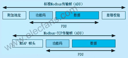
In different communication methods, Modbus PDU must be encapsulated to form different Modbus frames. This frame has a proprietary term in the Modbus protocol called Application Data Unit (ADU). In Modbus-RTU and Modbus-Plus communication, the standard application data unit is used. It only adds an additional address occupying one byte in front of the PDU and adds a check code occupying two bytes at the end of the PDU. In Modbus-TCP / IP network communication, the Modbus application layer protocol needs to be re-encapsulated. This encapsulation is achieved by adding the Modbus application layer protocol frame header before the Modbus PDU.
Table 2 Comparison of three Modbus communication methods with OSI reference model 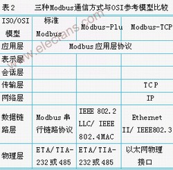
The Modbus communication network based on the serial link is a master-slave network. Only one master node and a maximum of 247 slave nodes are allowed in the serial network. Under this network, the additional address field in the standard Modbus ADU is only Contains the address of the slave node, the addressable range is 0 ~ 247, address 0 is used as the address of the broadcast mode, the valid value range of the slave node address is 1 ~ 247, and the address of each slave node must be unique, the master node There is no specific address value. The master node device puts the address of the slave node device to be accessed into the address field of the request frame. When the slave node device of this address responds, it will copy the address of the slave node device into the address field of the response frame. The node device knows which slave device sent the response through the address.
The check field stores the result calculated by the redundancy check algorithm according to the content of the message. There are two transmission methods in the Modbus communication network based on serial link: RTU and ASCII, the redundancy check algorithm of these two transmission methods is different.
The RTU communication mode can transmit more information than the ASCII mode at the same baud rate. Under the RTU mode, the transmission data is encoded in binary encoding. Each byte (8 binary bits) in the message contains Two hexadecimal characters, the characters in the same message must be transmitted continuously. The RTU mode byte transmission format consists of 1 start bit, 8 data bits, 1 parity check bit, and 1 stop bit in sequence, occupying a total of 11 binary bits. When the parity check is not used, the parity bit is also used as a stop bit. At this time, there are two stop bits. The error check field of the frame under the RTU transmission mode stores the result calculated by the cyclic redundancy check (CRC) algorithm.
When using the ASCII communication mode, each byte (8-bit binary) is represented by two ASCII characters. Since each byte must be represented by two characters, the length of the data field is twice that of the RTU mode. Obviously, the transmission efficiency in this mode is lower than that of the RTU mode. The byte transmission format of this mode is similar to the RTU mode, except that the data position occupies 7 binary bits. The error checking algorithm for frames in ASCII mode is longitudinal redundancy check (LRC). 
Modbus-TCP implements Modbus message communication in TCP / IP Ethernet as a client / server. This communication model is constructed by embedding Modbus protocol as the application layer protocol in the low-level TCP / IP protocol. Compared with the standard Modbus frame, the addressing and verification in the Modbus-TCP frame are completed by the TCP / IP protocol. As shown in Figure 3, the Modbus PDU is embedded in the TCP message using the encapsulation method to form a Modbus-TCP frame. This frame forms an MBAP frame header occupying 7 bytes before the PDU. The frame header can be divided into four Part, as shown in Table 3.
The transaction identifier is used for transaction verification. The server-side node receives the request transaction identifier sent by the client and copies it to the response. The protocol identifier is used for multiplex transmission within the system. When the value is 0, it represents Modbus protocol transmission. The length field records the byte length of subsequent messages in this field (including the device identifier and data field) and is used by the server to identify the end of the message transmission. The device identifier is used for routing within the system. When communicating with a device on a Modbus serial link or Modbus-Plus communication network connected via an Ethernet gateway, the value of this identifier field is requested by the Modbus-TCP client in the request frame After setting, the server will copy the value in the response frame.
For the Quantum series PLC under Schneider Electric, in order to speed up the completion of this work, the self-written program is used to realize the direct operation of the computer on the four data types of the PLC. In terms of hardware, the Quantum series PLC has a network module that can provide an Ethernet interface, and communicates with the CPU through the backplane. It serves as a server for Modbus-TCP communication and does not require us to do other programming work. The PLC defines four independent memory areas for the four data types stated above, of which discrete input is area 1, coil is area 0, input register is area 3, output register is area 4, addressing mode is area number plus The upper 5 digits of the decimal address. When the input address is less than 6 digits, the system will automatically assume that the highest digit value is the memory partition number, and the subsequent value is the address number in this area. Since the purpose of the operation is to check the correctness of the IO channel in the PLC system, the required function codes are: read coil 01, read discrete input 02, read holding register 03, read input register 04, write multi-coil 15 and write multiple Register 16.
A complete Modbus-TCP communication can be divided into three steps in time: connection establishment, Modbus data transmission and connection release. Before performing Modbus data transmission, a connection must first be established. The device allows a new connection and data transmission with other devices by providing a listening port (socket) on port 502. When a device needs to exchange data with a remote server, it must establish a connection with the server's port 502 through its own port greater than 1024. After the TCP connection is established, the client device can send a Modbus request frame to the server. The server responds after receiving the request and sends a response message to the port connecting the client. At the end of the transmission, the client is responsible for initializing the release of the communication connection.
The program runs in DOS mode and provides the following operating parameters:
-ip: the IP address of the target server;
-p: Modbus communication port of PLC, the default value is 502;
-c: the number of operation objects that the server executes the function code;
-r: start address of the operation;
-w: write operation parameters;
-a: automatic operation mode;
-t: time interval for automatic operation;
-b: Boolean value for coil write operation.
Through the Ethernet, the computer directly reads and writes PLC data, so that the plant-level monitoring network can directly communicate with the field devices. The monitoring personnel can detect the PLC channel on the familiar computer screen, compared with relying on artificially applied signals for detection. The former obviously reduces the workload of the operator, and when the number of IO points to be detected is larger, the efficiency is higher. This program is just a simple application of Modbus and TCP / IP protocol. Although the real-time, stability and anti-interference of Ethernet have been greatly developed, there are still many to apply Ethernet to actual control. Technical difficulties, it still has a long way to go. However, it is an inevitable trend for Ethernet to enter the field of automatic control. It will make control easier and clearer.