Abstract: Based on the hardware and software design and debugging of the microcontroller system and the successful system integration and debugging, the system design of the vehicle MP3 is completed. Using the mature technology of the single-chip technology, the microprocessor P89LPC935 is used as the main control device, and the control of the whole system is completed by extending the peripheral circuit. The car MP3 system is designed to play MP3 audio files and FM stereo radio on USB mass storage devices. This article refers to the address: http:// O Introduction In today's digital age, multimedia technology is the fastest growing and most active technology in the field of information technology, and is the focus of the development and competition of the new generation of electronic technology. And specialized digital audio-visual products have also entered the car in large quantities, such as CD, VCD, DVD and other equipment. The vehicle MP3 system completed by this design mainly includes 6 modules: control module, digital audio processing module, analog audio processing module, radio module, keyboard control module and liquid crystal display module. The entire system is designed around two CPUs, the microprocessor P89LPC935 and the AT89C5l-SNDI with decoder. According to the design requirements, the car MP3 application design system has completed the MP3 audio file and FM stereo radio function on the USB mass storage device. 1 system overall design 2 hardware system design 3 system software design Design a USB system, in order to make it work properly, it is necessary to design the software. The system software design of the car MP3 is divided into three parts: (1) the firmware of the USB peripheral (Firm-ware) program; (2) the client driver on the host operating system; (3) the host application software. The firmware of the single-chip microcomputer responds to various USB standard requests from the system, and completes various data exchange work and event processing; the client driver allows the host to recognize the USB device, and reads the USB device through the application software to complete the communication function; the host application The software communicates with the system USB (USB Device Interface) through the client driver, and the system generates USB data transfer actions. Including detection enumeration program, interrupt service, human machine interface, file operation function set, FAT file system function set, USB protocol layer, hardware extraction layer, data conversion program. 4 System debugging After the software and hardware of the MCU application system are completed, it must be debugged and modified repeatedly until it is fully working. Commissioning can usually be done in three steps. 5 Conclusion After the system software and hardware design and debugging, and on the basis of successful system integration and debugging, the system design of the car MP3 was completed. The car MP3 system design has USB disc stereo playback and FM stereo radio. Abandoning the CD and tape playback functions in the traditional audio system, it has the advantages of electronic shock resistance and strong anti-interference. It can download the latest MP3 songs at any time according to the storage size of the USB disk, eliminating the need to purchase a large amount of discs, and the machine With power-down memory and on-site protection.
Super AC Contactor is exactly copy schneider newest model.The up parts and base will be easy opened to change the coils. On the top of Magnetic AC Contactors, there is a transparent cover for dust improved purpose.
Super AC Contactor is suitable for using in the circuits up to the rated voltage 660V AC 50Hz or 60Hz,rated current 95A.It's mainly used for making and breaking electric circuits at a long distance and for frequent starting/stopping & controlling AC motors. Combined with the auxiliary contact group,air delayer,machine interlocking devence etc,it is combined into the delay contactor,mechanical interlocking device etc,it is combined into the delay contactor,mechanical interlocking contactor,startriangle starter,with the Thermal Relay,it is combined into the electromagnetic starer.
Super AC Contactor Super AC Contactor,Electric Magnetic Contactor,Alternating Current Contactor,AC Contactor Alternating Current Ningbo Bond Industrial Electric Co., Ltd. , http://www.bondelectro.com
Keywords: MP3; system design; P89LPC935; FM; USB
1.1 The overall design of the car MP3 system For any car MP3 system, the main work of its design is the choice of system structure, the rational distribution of hardware and software functions, the design of the operation panel. 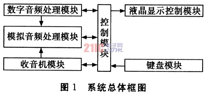
Here, according to the functions that the system needs to complete, the overall design scheme block diagram of the car MP3 system shown in FIG. 1 is drawn. The system mainly includes six modules: digital audio processing module, analog audio processing module, control module, radio module, keyboard module, liquid crystal display control module. The entire system is designed around two microprocessors P89LPC935 and AT89C51-SNDI with decoder.
1.1.1 Hardware System Composition A good intelligent instrumentation must have a good hardware system to be able to complete the transmission, conversion and storage of data on site. The overall design of the hardware part of the car MP3 system should first select a cost-effective, system-level CPU chip, and then expand on it, select other components, design the circuit part with it, and form the hardware system after debugging. .
The core chips used in the hardware design of the car MP3 are the microprocessors AT89C51SNDI and P89LPC935.
1.1.2 Software System Composition Designing a system for car MP3, software design is essential. The software design of the car MP3 system is divided into two parts:
AT89C51SND1: The MCU responds to various USB standard requests from the system to complete various data exchange and event processing. The client driver allows the host to recognize the USB device and access the USB device through the application software to complete the communication function. .
2.1 Structure of the hardware system The integrated chip used in the system design of the car MP3 includes: a microcontroller with a decoder (AT89C51 SND1), a microcontroller (P89LPC935), and a four-channel sound quality processor (PT23-13L). ), USB interface chip (SL811HS), static RAM (CY62256), radio chip (TEA5767H), audio power amplifier (TDA7384), audio digital-to-analog converter (PCMl754), liquid crystal display control chip (UPDl6431A). The hardware block diagram is shown in Figure 2. 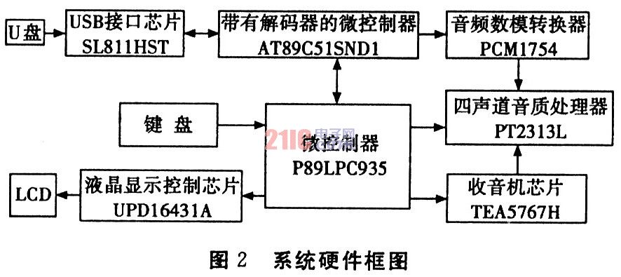
2.2 Hardware design of control module The working state of the whole system is divided into two states: closed state and working state.
When downloading (burning), its peripheral circuits are all powered off, only the P89LPC935 has power and is powered by a computer. Its 5 V operating power supply is connected to the computer via a 6-pin double-row pin. 
2.3 Hardware design of the radio module The digitally tuned radio module with frequency modulation from 87.5 MHz to 108 MHz uses the portable, low-power FM stereo radio chip TEA5767HN. The operating voltage is low and requires few and low cost peripheral circuits. Thanks to the integrated low noise RF input amplifier, it has a high sensitivity; a freely adjustable stereo decoder, a phase-locked loop synthesizer for the tuning system. There are two types of buses to choose from via the BUSMODE: I2C bus and 3-wire bus. This system selects the I2C bus, which sets BUSMODE to O. Figure 4 shows the hardware design circuit of the TEA5767HN. 
3.1 Car MP3 system design workflow description 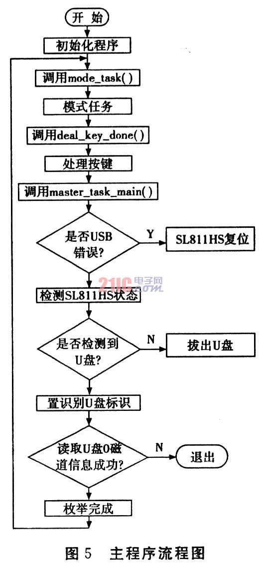
3.2 Endpoint Configuration Stage Programming The program structure framework of the firmware mentioned above can be based on interrupt or query-based. Here, the query mode is taken as an example. For a USB Mass Storage device, data processing for 3 endpoints must be supported.
(1) End of O: The control endpoint is used to control the transmission. The host reads the device descriptor through the pipeline corresponding to the endpoint O, completes the setting of the device address, and completes the configuration. This endpoint is a two-way data transfer endpoint.
(2) Two non-O endpoints: bulk transfer endpoints. Such endpoints are unidirectional data transmission endpoints, which are Bulk-In endpoints and Bull-Out endpoints, respectively.
3.3 Device Configuration Stage Program Design Once the USB device is plugged into the USB interface of the PC, after USB detects that the device is plugged in, it will send a USB standard request to the default address through the control pipeline to enter the device configuration phase.
The configuration phase is the process by which the host requests various descriptors from the device. Each time the device receives data from the host, it triggers the bit represented by endpoint O in the endpoint interrupt register. At this point, the data buffer of endpoint O should be read and the data of the specified length (length represented by the UBYCTX register) read. The request type is then identified against the data format requested by the USB standard device and then redirected to the corresponding standard request handler.
3.4 BulkOnly Program Design According to the USB protocol, the control pipeline is a message pipeline, and the information in the control pipeline has a fixed format. Other pipes are flow pipes, data in the flow pipes, and the format is not specified in the USB protocol.
The Mass Storage protocol transmits commands and data through Bulk transmission. In this transmission mode, there are three types of data (CBW, CSW and normal data) transmitted between the USB and the device. Both CBW and CSW data have a certain format, and ordinary data determines its attribution and meaning according to its previous command block. Therefore, the task of the batch transmission phase design is to identify the CBW data from the BulkOut endpoint for corresponding processing, and then return the corresponding CSW or data to the host through the BulkIn endpoint.
3.5 Play task In USB playback mode, press the repeat key to turn on the repeat play function. At this time, you can repeat the current track continuously. Click the fast reverse button or the fast forward button to select the track you want to repeat. Click this button again. Cancel the repeat play function. After entering this function, the “RPT†character on the LCD will be illuminated. Press the browse button to open the browse function, you can play the first few seconds of each track in sequence. At this time, you can click the fast reverse button or the fast forward button to browse the track backwards or forwards. When you hear the track you want to select, rotate the volume. The button plays the selected track and cancels the function. After entering this function, the “INT†character on the LCD will be illuminated. Press the random button to turn on the random play function. At this time, the unit will play the tracks randomly instead of playing the tracks in the USB disk in the normal playback order. Press the fast back button or the fast forward button to play other tracks randomly, click again. This button cancels the shuffle function. After entering this function, the “RDM†character on the LCD will be illuminated. Press the Pause/Play button to pause or play the track. When the playback is paused, the “STOP ON†character is displayed on the LCD.
(1) Hardware debugging First, use the logic pen, multimeter and other tools to check the hardware circuit offline to see if the connection is consistent with the logic diagram, whether there is short circuit or virtual soldering. The model, specifications, and polarity of the device are correct, and the plugging direction is correct. After the inspection is completed, the resistance between the positive and negative power terminals of the circuit board can be measured by a universal meter to eliminate the possibility of short circuit of the power supply.
When power-on check, you can simulate various input signals to be sent to the relevant parts of the circuit, observe the I/O port, check whether the components are overheated on the circuit board, and whether there is smoke or odor. Whether the action of each related device meets the design requirements.
(2) Software debugging Software debugging must be carried out with the support of the development system. First debug each module program, then debug the interrupt service program, and finally debug the main program, and connect the parts for debugging. The range of debugging can be increased from small to large, and the necessary intermediate signals can be set first. Usually, the single-step operation, the breakpoint operation, and the continuous operation are used in a crossover manner. After each execution, the CPU executes the scene, the contents of the RAM, and the status of the I/O port. Find a problem and solve a problem until it is all passed.
(3) Software and hardware joint debugging On the basis of successful software and hardware debugging, the software and hardware online simulation is performed. After the simulation is successful, the firmware program is written into the single-chip microcomputer, and the operation can be performed offline. 111")