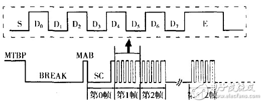
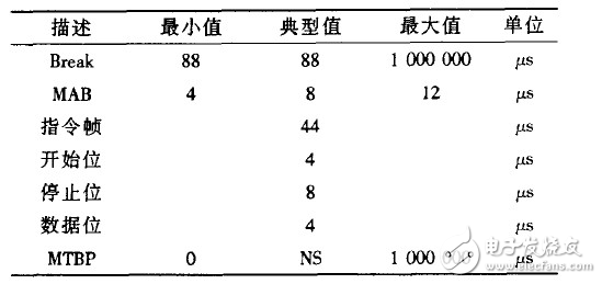
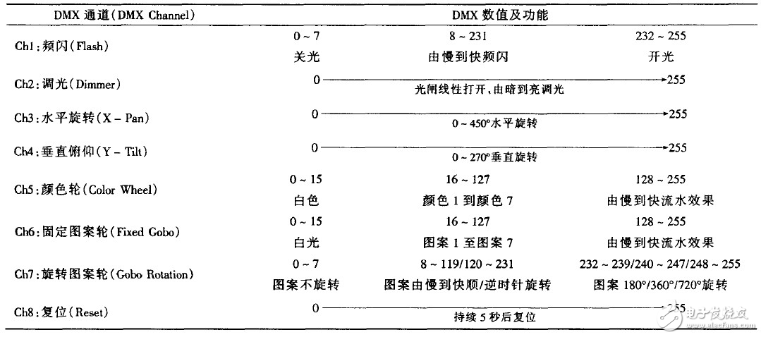
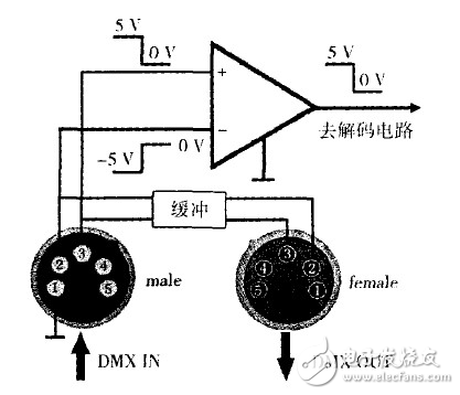
introduction The lighting system based on the DMX512 control protocol for dimming control is called a digital lighting system. At present, various stage lighting equipments such as computer lights, dimming controllers, consoles, color changers, electric booms, etc., have fully realized dimming with full support for the DMX512 protocol. The digitization of control, and on this basis, gradually become computerized and networked. Therefore, for film and television lighting design and operators, it is necessary to understand the program structure, control principle and application points of the DMX512 control protocol. 1. DMX512 lighting control protocol DMX is the abbreviation of Digital MulTIpleX, which means multi-channel digital transmission. The DMX512 control protocol is the industry standard for data transmission of lighting controllers and lighting equipment released by the US Stage Lighting Association (usITT) in 1990. The full name is USITT DMX512 (1990), including electrical characteristics, data protocols, data formats, etc. . Each DMX control byte is called an instruction frame and is called a control channel that controls one or more functions of the lighting device. A DMX instruction frame consists of one start bit, eight data bits, and two end bits, a total of ll bits, using one-way asynchronous serial transmission, as shown in Figure 1. Figure 1 DMX512 timing program frame structure (top) and packet structure (below) S in the control instruction in the dotted line in Figure 1 is the start bit, the width is one bit, which is the start flag of the controlled luminaire ready to receive and decode the control data; E is the end bit, the width is two bits, indicating the end of an instruction frame ; D0 D7 is 8-bit control data, its level combination from 0000 ~ a l1111111 has a total of 256 states (corresponding to 0 to 255 decimal), when controlling the brightness of the light, can produce 256 brightness levels, 0000~ (0) Corresponding to the darkest light, l1111111 (255) corresponds to the brightest light. The bit width (bit width per bit) of the DMX512 instruction is 4 s, with a width of 44 s per frame and a transfer rate of 250 kbps. A complete DMX512 packet consists of an MTBP bit, a Break bit, a MAB bit, an SC, and 512 data frames. MTBP (Mark TIme Between Packets) marks the completion of a complete packet transmission, which is the "idle bit" of the next packet to be started, and is active high. Break is an interrupt bit, corresponding to the program reset phase after the end of a packet, and the width is not less than two frames (22 bits). The control data should be sent after the program reset ends, but since the first bit (ie, the start bit) of each data frame is low, it is necessary to use a high-level pulse interval before and after the two low-level pulses. The high-level pulse of separation is MAB (Mark After Break). When this pulse arrives, it means that the control of “new round†has started again. SC (STart Code) means to start the code frame (0th frame in Figure 1). Like the subsequent data frame, it is also composed of 11 bits. Except for the two high-level end bits, the other 9 bits are all It is low level, usually called 0th frame or 0th channel (Ch~nel No 0), which can be understood as a non-existent channel (NON~~istent Channe1). Table 1 DMX512 packet timing table Table 1 is the timing table of the DMX512 packet. The NS in the table means Nm Spec~ed. The width is not strictly limited. It is up to the programmer to decide. For example, the width of the MTBP can be between 0 and 1 second. Each time a dimming console sends a packet, it can form a full control of all 512 controlled channels. The time to send a packet is about 23IIls, and 44 control is performed for all 512 controlled channels every second, that is, the refresh rate of the controlled optical path is 44 Hz. If the actual controlled channel is less than 512, the refresh frequency will be Increase accordingly. 2. The basic mechanism of the DMX512 protocol A DMX interface can control up to 5l2 channels, because computer lights generally have several to dozens of functions. A computer light needs to occupy a few, dozens of control channels. Let's take a look at the control process and principle of the DMx5l2 through a DMX channel table with a simple function and a small number of small computer lights. The computer lamp has eight DMX control channels, one color wheel and two pattern wheels, which have the functions of dimming, stroboscopic, shaking head and changing light color and pattern. The DMX channel serial number, channel coding and corresponding functions are shown in Table 2. Show. Table 2 DMX channel table of computer lights The DMX values ​​in Table 2 are represented by decimal numbers, and the binary combination of 0 7 corresponding to 8-bit control data is 00000~0 000001 1 1. The binary combination corresponding to 232 to 255 is 11101000 to 11111111, and so on. The process of decoding a part or all of the 8-bit binary of an instruction frame in the DMX protocol to form a function or a state change of the computer lamp is decoding and control. It can be clearly seen from the DMX channel table that the function of the computer light, the number of channels and their corresponding relationship are important basis for calculating the number of unit loads carried by a DMX interface and setting the starting address code. For example, like this kind of computer light with only 8 channels, a DMX interface can control 64 units (512/8=64). If the number of DMX channels of another computer is 20, then the number of DMX interfaces that can be controlled is 25 (512/20=25.6, the remainder is discarded). 3. Several application problems of DMX5 12 control protocol When using the DMX512 protocol to control digital lighting equipment, you need to understand the application characteristics, starting address code, unit load and signal terminator of the DMX interface. 3.1 Application characteristics of DMX interface DMX512 standard stipulates that the DMX interface uses a 5-core card with a core, 2 cores, 2, 3 and 4, 5 core transmission control signals (2, 4 for the inverting terminal, 3, 5 for the in-phase terminal), 4, 5 core It is intended to transmit information such as the status of the lighting equipment and error detection, and then idle. The reason why the 5-core card is used instead of the more common 3-pin card is to prevent accidental connection with the 3-pin card that is commonly used on professional audio, because the condenser microphone is connected to the audio device. The core card can provide 48 v phantom voltage to the outside. This kind of wrong connection can easily burn out the internal circuit. Despite this, many computer lights still use a 3-pin card. If two types of card ports are coexisting, use an adapter to properly transfer them. All digital lighting equipment has a DMX input interface and a DMX output interface. The DMX512 control protocol allows a variety of lighting equipment to be connected in a mixed manner. In use, the DMX output interface of the previous device can be directly connected to the input interface of the next device. stand up. However, it should be clear that this seemingly serial link architecture is actually parallel to the DMX control signals. Because the DMX control signal enters the lighting device and then “two channels†(see Figure 2), after the voltage comparison and amplification and shaping of the op amp circuit, the command pulse is decoded, and then the stepping motor is controlled by the driving circuit to complete various Control action; the other way is buffered, isolated, and sent directly to the next lighting device. In addition, it is not difficult to draw a conclusion from the voltage comparison effect of the op amp in Figure 2. The high common mode rejection capability of the op amp circuit can greatly improve the anti-interference ability of the DMX control signal, which is why the DMX512 control The signal is balanced for transmission. Figure 2 Lighting device DMX interface simplified circuit 3.2 Starting address code Each lighting device based on the DMX512 control protocol needs to be assigned a digital start address number, which is the address code of the lighting device. The address code is used for addressing the DMX512 control signals to ensure that the device reacts only to control signals that are "own". The address code is actually the starting serial number of the lighting device control channel. When the channel number (frame number) of the DMX512 packet is the same as the address number of the channel to which the lighting device is assigned, the device starts decoding the DMX512 control signal and generates a control action. At the same time, other lighting devices on the same link do not respond to the DM~12 control signals. Until the control channel number of the DMX512 packet transitions to the same as the channel start sequence number given by the next lighting device, the device stops controlling, and the address code of the next lighting device functions and is in a controlled state. Taking a computer light as an example, if a DMX control port drives several computer lights, the starting address code of the first computer light is 001, and the starting address code of the second computer light is 001 plus the DMX channel of the first light. Number, and so on. For example, the number of channels of the first and second computer lights are l6 and 20 respectively, the starting address code of the first computer light is 001, the starting address code of the second computer light is 017, and the third computer The starting address code for the light is 037. The starting address code of the last computer light and its channel number must not exceed 512. If there are remaining computer lights, the console's next DMX control interface should be enabled. There are two ways to set the starting address code of the digital lighting device: digital and dialing. The overall setting method is relatively simple. 3.3 unit lights of unit lights (Units of Load) According to the DMX512 protocol standard, each DMX interface can only control up to 32 unit loads under the premise that the total number of channels of the controlled luminaire does not exceed 512. When computer lights, silicon boxes, color changers or other lighting equipment supporting DMX512 control protocol are more than 32, but the total number of control channels is far less than 512, DMX distributor can be used to divide one DMX signal into multiple DMX branches. On the one hand, it is convenient to connect the lighting equipment on the lamp holder nearby, and on the other hand, each branch can drive 32 unit loads. However, the total number of channels controlled by each DMX branch belonging to the same DMX link cannot exceed 512. 3.4 DMX Terminator (fDMX Terminator) The DMX terminator is a card slot connector connected to the DMX output interface of the last lighting device of each DMX branch. The connector is connected to a resistor with a resistance of 120 Q and a power of about 1 W. The end of the DMX branch is closed. Because the DMX control pulse frequency is high, when the transmission line is unreachable, it has the nature of the original return. In this way, the signal returned by the original path will be superimposed with the subsequent signal, which will easily cause the DMX control command to generate a bit error, so that the computer light is not normal. Decoding, the phenomenon of malfunction or control failure. Therefore, accessing a terminal on the DMX output interface of the last computer light is beneficial to ensure the stable operation of the computer light. 4. Summary Compared with the traditional analog dimming system, the digital lighting system based on the DMXS12 control protocol has brought about tremendous changes in the lighting effects of large and medium-sized film studios and variety stages with its powerful control functions. However, the DMX512 lighting control standard also has some shortcomings, such as the speed is not fast enough, the transmission distance is not far enough, the wiring and initial settings become too cumbersome as the system scale becomes larger, and the control data can only be controlled from the control terminal to the controlled unit. One-way transmission, can not detect the working condition and online status of the luminaire, and is prone to transmission errors. Later, the revised DMX512-A standard supports two-way transmission, which can return information such as erroneous diagnosis reports of lamps and is compatible with all DMX512-compliant lighting equipment. In addition, some lighting equipment's decoding circuits support 12-bit and 12-bit data expansion modes for more precise control. Dmx512 related articles: How to connect dmx512 decoder? Dmx512 decoder wiring diagram What is the function and characteristics of the dmx512 controller (working principle and wiring diagram) DMX512 controller description and introduction, DMX512 controller instructions Household Electric Water Kettle,Mobile Quick Boiling Water Kettle,,Kitchen Tools JOYOUNG COMPANY LIMITED , https://www.globaljoyoung.com