Central issue: 1 Working principle 2 system configuration of four quadrant inverter
Aluminium Alloy Phone Ring Holder
Aluminum alloy ring custom: Aluminum alloy ring are mainly made of aluminum alloy, zinc alloy, Using a new type of nano enhanced adsorption soft mobile phone not afraid of falling,Can be washed dry, you can restore as before;With car hook more heart,Metalmatte texture color is rich.
Aluminium Alloy Phone Ring Holder Aluminium Alloy Phone Ring Holder,Portable Aluminium Alloy Phone Ring Holder,Aluminum Alloy Phone Stand Ring Holder,360 Rotation Phone Ring Holder Dongguan Qilong Electronic Co., Ltd. , http://www.venicen-ringholder.com
• Working principle of four-quadrant inverter • System configuration of four-quadrant inverter • System control scheme for rectification part of four-quadrant inverter
solution:
•Composed of AC contactor, power resistor and corresponding control loop • Rectifier side and inverter side IGBT, isolated drive, current detection and various protection monitoring functions • Reduced output dv/dt, which protects the motor
In the late 1980s, AC variable frequency speed control gradually entered the historical stage of industrial transmission speed control. The frequency conversion speed regulation has great advantages in the speed regulation range, speed regulation precision, control flexibility, work efficiency, convenient use, etc., which makes the frequency conversion speed regulation become the most promising mode of the AC speed regulation.
Ordinary inverters mostly use a diode rectifier bridge to convert AC power into DC, and then use IGBT inverter technology to convert DC into an AC motor with adjustable voltage and frequency. This kind of frequency converter can only work in the electric state, so it is called two-quadrant frequency converter. Since the two-quadrant inverter uses a diode rectifier bridge, two-way flow of energy cannot be achieved, so there is no way to return the energy of the motor feedback system back to the grid. In some applications where the motor needs to feed back energy, such as elevators, lifts, and centrifuge systems, the resistance braking unit can only be added to the two-quadrant frequency converter. The energy returned by the motor is consumed. In addition, in some high-power applications, diode rectifier bridges cause severe harmonic pollution to the power grid.
The IGBT power module can realize the bidirectional flow of energy. If the IGBT is used as the rectifier bridge, the PWM control pulse is generated by the DSP with high speed and high computing power. On the one hand, the input power factor can be adjusted to eliminate harmonic pollution to the power grid, making the inverter truly a "green product." On the other hand, the energy generated by the motor feedback can be sent back to the grid to achieve a complete energy saving effect.
Since 2001, Jina Motor has been developing and developing four-quadrant inverters. Up to now, it has formed mature products and technologies of two series of power levels of 380V and 660V, and is widely used in coal mines and oil fields.
The working principle of four quadrant inverter
The circuit schematic of the four-quadrant inverter is shown in Figure 1. 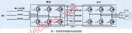
When the motor is in the motoring state, the DSP of the rectifier control unit generates six high-frequency PWM pulses to control the turn-on and turn-off of the six IGBTs on the rectifier side. The turn-on and turn-off of the IGBT interacts with the input reactor to produce a sinusoidal current waveform that is in phase with the input voltage, thus eliminating the 6K±1 harmonics generated by the diode bridge. The power factor is as high as 99%. Harmonic pollution to the grid is eliminated.
At this time, the energy flows from the grid to the motor via the rectification loop and the inverter loop, and the inverter operates in the first and third quadrants. The waveforms of the input voltage and input current are shown in Figure 2. 
When the motor is in the power generation state, the energy generated by the motor is fed back to the DC bus through the diode on the inverter side. When the DC bus voltage exceeds a certain value, the rectifier side energy feedback control part is activated, and the DC is inverted into an AC, and the control is performed. The inverter voltage phase and amplitude feed back energy to the grid to achieve energy savings.
At this time, the energy flows from the motor to the grid through the inverter side and the rectification side. The inverter works in the second and fourth quadrants. The main function of the input reactor is current filtering. The feedback current and grid voltage waveform are shown in Figure 3: 
(1) The composition of the main circuit: pre-charge circuit, input reactance, intelligent power module, electrolytic capacitor and output reactance. The functions of each part are listed below:
• Pre-charge circuit: consists of AC contactor, power resistor and corresponding control loop. The main function is to complete the pre-charging of the DC bus capacitor when the system is powered on. Avoid strong inrush current when powering up to burn out the power module.
• Input reactor: The energy storage function in the electric state to form a sinusoidal current waveform. In the feedback state, it acts as a filter to filter out the high frequency components of the current waveform.
• Intelligent Power Module (SkiiP): Rectifier side and inverter side IGBT, isolated drive, current detection and various protection monitoring functions.
• Electrolytic capacitor: energy storage, filtering.
• Output reactance: reduce the output dv/dt, which has a certain protection effect on the motor.
(2) Control part: system auxiliary power module, pre-charge control, power interface board, DSP control board and human-machine interface board.
• The system auxiliary power supply generates the 5V, 15V and 24V power supplies required for system control;
• Pre-charge control is used to control the action of the pre-charged AC contactor;
• The power interface board feedback system controls the required current, voltage and temperature signals and passes the PWM control waveform to the driver board. The interface board needs to filter the signal;
• DSP control board completes rectification, inverter PWM control algorithm, and system brain.
• The HMI displays various conditions of the drive operation and user parameter inputs.
Rectification section The control section of the rectifier section system is shown in Figure 4. 
As shown in Figure 4, the system is given the DC bus voltage command, and the error of this command and DC bus voltage feedback is sent to the PI regulator of the voltage loop. The PI regulation of the voltage loop and the product of the three-phase input sine wave become the command of the three-phase current. The three-phase current command is compared with the respective current feed, and the error is sent to the PI regulator of the current loop. The output of the current loop PI regulator can generate PWM control signals of each phase IGBT through carrier modulation, or can generate PWM signals to control the IGBT by means of space vector. The above operations are all done by DSP.
typical application
Typical applications for four-quadrant inverters are those with potential load characteristics, such as drop machines, locomotive traction, oil field boring machines, centrifuges, etc. In some high-power applications, four-quadrant inverters are also needed to reduce harmonic pollution to the grid.
The application of the hoist is reversed. When lifting heavy objects, the four-quadrant drive motor drives the motor to overcome the gravity work, and the motor is in the electric state. When the heavy object is placed, the excitation current is generated on the inverter side, the gravity traction motor generates electricity, and the motor is in the power generation state. The potential energy is converted into a grid that is fed back through the rectification side.
The inverter with PWM control rectifier has the function of four-quadrant operation, which can meet the speed regulation requirements of various potential loads, and can convert the regenerative energy of the motor into electric energy and send it back to the grid to achieve the maximum energy saving. Not only that, it also reduces the harmonic pollution of the power supply, the power factor can be close to 1, is a true "green" inverter.
It also called: mobile phone ring brackets, mobile phone buckle, finger buckle, mobile phone ring, ring bracket, mobile phone holder, 360 bracket, ring frame, mobile phone grip Mobile phone ring frame, iphone mobile phone bracket, ring bracket, finger buckle hook, mobile phone ring bracket.
We also can customize Logo and accroding to your demand products you want. Some design gift is also can be customized. There is nothing we cannot do but something you cannot predict.
Four quadrant inverter technology introduction
Four quadrant inverter technology introduction