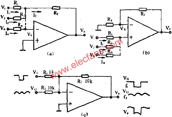
The figure shows an adder consisting of a general-purpose Type I F004 op amp. This article refers to the address: http:// The adder is an amplifier whose output signal is the sum of several input signals, and is divided into an inverting adder and an in-phase adder. In the figure, A is an inverting adder circuit, as can be seen from the figure
Fused Biconic Taper (FBT) splitter, also be called fiber coupler, based on the traditional technology, it is to bundle together two or more optical fibers, and then pull the cone machine melt stretching, and real-time monitoring the change of the ratio, spectral ratio requirements after melt stretching, one side retain a single fiber (the rest of the cut) as input, the other end is a multi-channel output.
As one of the key components for GPON FTTx networks, optical splitters can be placed in the Central Office or in one of the distribution points (outdoor or indoor) because the FBT splitters are highly stable for multiport optical signal splitting with low insertion loss. FBT couplers are designed for power splitting and tapping in telecommunication equipment, CATV network, and test equipment
XRX FBT splitters are available with 1x2, 1x3, 1x4, 1x5, 1x6, 1x8, 1x12, 1x16, 1x18, 1x20 and 1x24 configurations with single mode or multimode fiber and we offer all type connectors of pre-connectorized like SC, FC, ST, LC and E2000 etc.
Fiber Splitter,Window Splitter,Optical Wire Splitter,Three Windows Splitter Chengdu Xinruixin Optical Communication Technology Co.,Ltd , http://www.xrxoptics.com