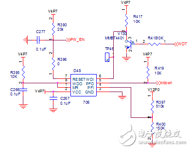
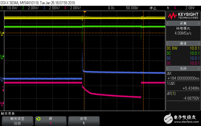
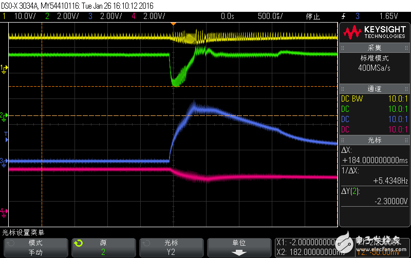
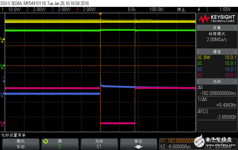
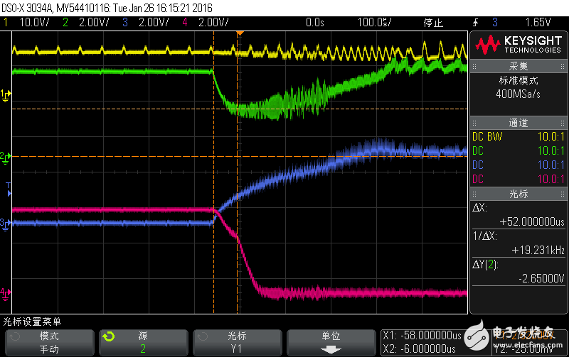
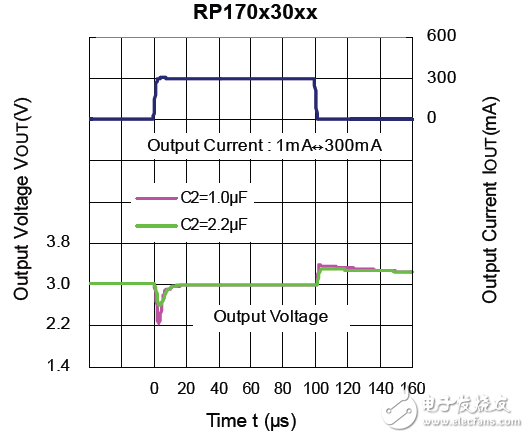
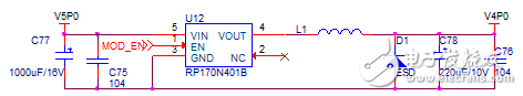
Conventional DC-DC generally requires that the input and output voltage difference be above 2~3V. With the development of the times, such conditions can no longer meet the needs of practical applications. For example, in the field of wireless communication, the voltage commonly used by the GPRS module is 4V, which is often converted by 5V, and the input and output voltage difference needs to be as low as 1V. In response to such a situation, LDO (Low dropout regulator) came into being. Compared with DC-DC, LDO has the advantages of low noise and small quiescent current. Many DC-DCs also need inductors and freewheeling diodes in the peripheral circuits. The typical circuit of LDOs is very simple. Many LDOs only need to connect a bypass capacitor at the input and output terminals to stabilize the operation. The layout space is also very advantageous. Many LMOs introduced by Ricoh also have other functions such as load short circuit protection, over voltage shutdown, thermal shutdown, reverse connection protection and so on. Many hardware engineers mainly consider the input voltage range, output voltage and current, voltage difference, ripple, power consumption, quiescent current, etc. in LDO applications, but often ignore a very important parameter: load regulation. This article is about the problem that I used to ignore the load adjustment rate when I applied Ricoh's RP170N401B, and finally shared some of my own experience by improving the design to solve the process. Problem Description The author's circuit is shown in Figure 1. The system 12V is converted to 5V, and 5V is converted to 3.3V and 4V for the MCU and communication module respectively. Since the communication module is turned on and off periodically, it is found that as long as the enable pin of U12 (RP170N401B) is low, the system can work normally. When MOD_EN is pulled high, the whole system is reset. Figure 1: The original schematic of the author's design problem analysis The author initially suspected that the 4V back-end circuit was short-circuited, causing the 5V power supply to be pulled down, but this problem occurred because of the 6 prototypes, and the possibility of 4V short-circuit was eliminated. In fact, there is also a design of watchdog and power supply monitoring in the circuit. As shown in Figure 2, the problem occurs here. The PW_EN pin directly controls the LDO chip of 5V to 3.3V. Figure 2: Watchdog circuit The author first measured the waveform of each power supply of the system when MOD_EN was pulled high, and the waveform is shown in Figure 3. Figure 3: System power waveforms Waveform analysis: In the figure, the waveforms are 12V, 5V, 4V, and 3.3V from top to bottom. In the figure, 3.3V is pulled down by 184ms. You need to look further at the peak details of the 5V and 4V power lines. After the above waveform is amplified, a waveform diagram as shown in FIG. 4 is obtained. Figure 4: System power waveform amplification Waveform analysis: 12V, 5V, 4V, 3.3V waveform details in order from top to bottom. In the figure, the 5V voltage is pulled to 2.3V. When the voltage is lower than 2.63V, the 706 will output a 200mS reset signal. The measured time is 184mS. Within the measurement error range, similar to the power monitoring reset time of 706, the reset signal of 706 can be continuously monitored, and the waveforms shown in Figures 5 and 6 are obtained. Figure 5: Reset signal for watchdog 706 Waveform analysis: 12V, 5V, 4V, PW_EN waveform details in order from top to bottom. At the moment of 4V transition, RST outputs a low-level reset signal, which pulls the 5V to 3.3V LDO enable pin. Figure 6: Reset Waveform Details Waveform analysis: Before the 5V fall back to 3V, the watchdog 706 outputs a low-level reset signal, and the reset signal is divided into two segments. The inflection point appears before and after the power supply voltage is 2.65V. The falling waveform before the inflection point is with the 5V power supply. The voltage falls synchronously; and the falling waveform after the inflection point is a reset signal that the watchdog chip 706 detects that the power supply voltage is lower than the 2.63V output. Figure 7: Load Regulation on the RP170N401B Manual By looking at the device manual of the RP170N401B, it is found that when the load suddenly becomes large, the output voltage drops instantaneously due to the inability to adjust in time. Corresponding to the system, when the LDO enable terminal of the 4V power supply is enabled, due to the load on the back end of the LDO, the impact of the instantaneous current causes the LDO input and output to have a certain instantaneous voltage drop. The system pulls the 12V down to 9.6V, Seriously, the 5V level is pulled down to 2.6V in 50us, and 4.7V is pulled down to 2.6V or less, causing the power monitoring chip 706 to output a reset signal, which causes the system to restart. improve proposals As can be seen from Figure 7, when the value of the LDO output is adjusted, the voltage drop will be flat, and the following two approaches are taken: 1) LDO output series inductance, through the saturation current of the inductor to suppress transient high current when the chip starts. 2) Adjust the topology of the capacitors at both ends of the LDO input and output, and eliminate the drop by capacitor energy storage. Figure 8: Improved circuit The load change rate of LDO is also a very important parameter, which is often a blind spot in the design. Finally, the author's circuit is shown in Figure 8. The inductance L1 is increased and the C77 is adjusted to 1000uF. The restart phenomenon is also successfully solved. Summary of experience In the application of LDO chips, the load regulation rate is also a very important parameter, which should be paid attention to at the beginning of the selection of new product design. For chips that have been used in old products, when the load regulation rate cannot meet the requirements of actual use, the power supply design can meet the system requirements by controlling the instantaneous power of the back-end load circuit and adjusting the topology of the LDO cascade. Make the product run stably and reliably. LAN WDM - LAN Wavelength Division Multiplex
LWDM is a wavelength division multiplexing Lan-WDM technology based on Ethernet channels. Its channel interval is 200~800GHz, this range is between DWDM (100GHz, 50GHz) and CWDM (about 3THz). LWDM uses 12 wavelengths in the O-band (1260nm~1360nm) range from 1269nm to 1332nm, with a wavelength interval of 4nm (1269.23, 1273.54, 1277.89, 1282.26, 1286.66, 1291.1, 1295.56, 1300.05, 1304.58, 1309.14, 1313.73 , 1318.35nm).
The characteristic of LWDM working wavelength is that it is located near zero dispersion, with small dispersion and good stability. At the same time, LWDM can support 12-wave 25G, the capacity is increased, and the optical fiber can be further saved.
LWDM Splitter, LAN WDM Splitter, LAN WDM Shenzhen GL-COM Technology CO.,LTD. , https://www.szglcom.com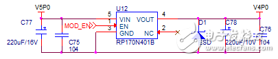


Channel 1: Wavelength 1313.73nm, reuse the DML-1310 wavelength in 100G CWDM applications. Starting from this wavelength, the channel spacing of the wavelengths is about 4.5nm;
Channel 2: Wavelength 1309.14nm, which reuses the DML wavelength in 100G LanWDM applications;
Channel 3: Wavelength 1304.58nm, reuse the DML wavelength in 100G LanWDM application;
Channel 4: Wavelength 1300.05nm, reuse the DML wavelength in 100G LanWDM applications;
Channel 5: Wavelength 1295.56nm, which reuses the DML wavelength in 100G LanWDM applications;
Channel 6: Wavelength 1291.10nm, reuse the DML-1290 wavelength in 100G CWDM applications;
Channel 7: wavelength 1286.66nm, reuse the EML wavelength in 400G LanWDM applications;
Channel 8: wavelength 1282.26nm, reuse the EML wavelength in 400G LanWDM applications;
Channel 9: The wavelength is 1277.89nm, which reuses the EML wavelength in 400G LanWDM applications;
Channel 10: wavelength 1273.54nm, reuse the EML wavelength in 400G LanWDM applications;
Channel 11: The wavelength is 1269.23nm, which reuses the DML-1270 wavelength in 100G CWDM applications.