1 Introduction Intelligent lighting systems are widely used in intelligent office buildings and modern buildings, but there are few research applications for teaching buildings, which leads to the widespread use of traditional lighting systems. The basic structure is that power lines are based on equipment control requirements. The split line uses a manual switch to directly control the power supply, and there is no concept of controlling the flow of information. This paper discusses the intelligent lighting system based on CAN/LIN bus, realizes centralized management of the whole system and reduces the management cost of the system. The use of dimmable electronic ballasts for constant illumination control, full use of daylight, truly achieves reasonable energy savings, creating a comfortable learning environment for students; soft start of the lamps, extending the service life and reducing the operating costs of the system. The Controller Area Network (CAN) is a new generation network communication protocol with open architecture and broadcast. CAN was first introduced for data communication between the internal measurement and execution components of the car. It can work reliably under strong electromagnetic interference environment with low cost and high real-time processing capability [1]. The LIN bus is a low-cost serial communication network that aims to provide accessibility to existing automotive networks such as the CAN bus. The use of the LIN bus can result in significant cost savings in situations where bandwidth and versatility of high-end automotive buses like CAN are not required. In LIN-implemented systems, analog semaphores are typically replaced with digital semaphores, which optimize bus performance. Therefore, the CAN/LIN bus quickly expanded from the original automotive industry to the industrial control field [2]. 2, system design The trunk line of this system adopts CAN bus, and the branch line adopts LIN bus. The CAN bus has high reliability, high speed and long distance transmission, and the development system is cheap. Its unique multi-master transmission mode enables each extension (node) to send data autonomously according to the need, without the host continuously polling, saving network. The data traffic on the high transmission efficiency. The above performance of the CAN bus has been solidified in the CAN bus processing chip, which is extremely convenient to use [3]. The LIN bus is based on a general-purpose UART interface. Almost all microcontrollers have the necessary hardware for LIN. The network uses very few signal lines (a 12V signal bus and a node-synchronous clock line with no fixed time reference), and the hardware cost of the device is low [ 2]. The function realized by the digital tunable electronic ballast intelligent lighting system [4]: (1) Decentralized control: Distribute control functions to each sub-controller of the system; (2) Fully automatic dimming: The lighting system works in a fully automatic state. The system can set several states. These states will automatically switch to each other according to the preset time, and the illumination will be automatically adjusted to the optimal working level. (3) The light-off state of the unit lamp can be observed on each control terminal panel; (4) Self-locking: If the power is cut off, all the lights will remain off after the call; (5) Automatic control combined with human intervention, setting switches on site to facilitate operation; (6) Monitoring and management of the entire lighting system can be realized in the monitoring room; 2.1 Hardware Design [5] (1) System unit: PC (with CAN interface card), system power supply, sub-monitoring unit (51 MCU 8LPC902) on each floor, and classroom controller (51 MCU 8LPC902). As the main controller, the PC issues and accepts information to each subunit, monitors the entire lighting system, and is responsible for the logic operation of constant illumination control. The sub-monitoring unit is mainly responsible for communication switching, and adds a CAN/LIN bus gateway to perform data conversion at the interface with the CAN bus. 2.2 Software Design The control program block diagram of the microcontroller on the LIN bus (shown in Figure 2): (1) Constant illumination control in intelligent lighting systems [6] After using the photoelectric sensor to measure the vertical illumination of the outdoor sunlight, input a RI model based on the genetic algorithm, estimate the indoor desktop illumination, and then compare with the set value to control the lighting switch, so as to maximize the use of natural light, To achieve energy savings, it can also provide a relatively stable visual environment that is unaffected by the seasons and the external environment. Compared with the use of the indoor illumination sensor, the model has the advantage of avoiding whether the natural light is sufficient to meet the illumination requirement and whether the artificial illumination is turned off in the next period of time when the artificial illumination is turned on. Generally speaking, the closer to the window, the higher the natural illuminance, the lower the illuminance provided by artificial lighting, but the synthetic illuminance should be maintained at the set illuminance value, as shown in Figure 3. The large group of activities - teaching building, development humanization of. Figure 3 indoor lighting diagram (2) Soft start 3 Conclusion The relationship between the attenuation of the attached light source and the life Make full use of natural light, save lighting power, intelligent dimming can greatly improve the life of lamps. The infrared monitoring function of the system avoids “long lightâ€, reduces man-made waste, reduces operation and maintenance costs, and brings considerable return on investment. The need for sustainable development is of great significance; it also has enormous ecological, environmental and economic benefits. This intelligent lighting system is also especially necessary for students.
The CAN/LIN bus control system is shown in Figure 1: 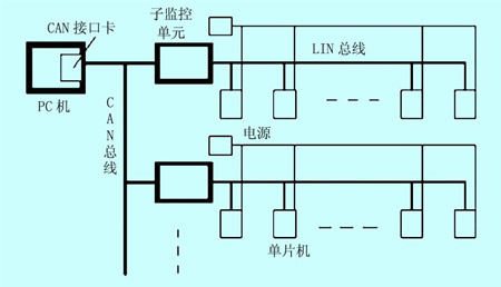
Figure 1 CAN / LIN bus control schematic
(2) Input unit: single/double/four-key switch, outdoor/indoor infrared sensor, illuminance sensor, photoelectric sensor, auxiliary input unit, which are used as the signal source of classroom controller, terminal controller on LIN bus The address number is set by the DIP switch, which is mainly responsible for signal acquisition and storage and response bus requirements release information. At the same time, the acquired signal is simply judged to determine the working state of each output unit. The terminal control MCU uses the LIN transceiver to accept the release signal, and the internal signal acquisition adopts the method of cyclic scanning and real-time updating.
(3) Output unit: single/double/four/12-way relay, four/eight-channel dimmer, and four analog output units.
(4) The teaching building corridor is treated as a terminal sub-unit. Using the infrared sensor as an input, the last illuminance calculation value of the main control unit is called to judge, and the illuminance sensor is not separately installed. 
Figure 2 terminal controller block diagram 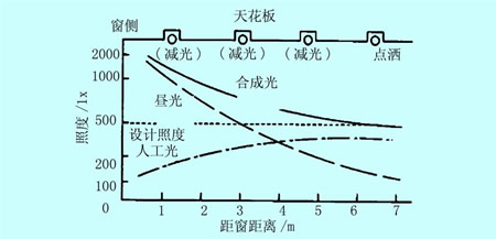
The lamp adopts a soft starter. When the lamp is turned on, the light gradually becomes brighter and darker, avoiding the sudden change of brightness to stimulate the human eye, giving the human eye a buffer time, protecting the student's eyes, avoiding the impact of the sudden change of the high current and high temperature on the filament. Light bulb for extended life.
(3) Master control program
PC management program is developed under Visual C++ under Windows2000 operating system, including system monitoring, communication management, data calculation, command output and keyboard display. When the system is running, the working status of each classroom light is displayed on the display of the PC in the form of a graphic. The display images of each layer can be switched to each other, and the image is intuitive and easy to operate [7].
The intelligent lighting system improves the lighting environment of the classroom. In the traditional lighting system, the fluorescent lamp with the traditional ballast flashes at a frequency of 100 Hz, and the brightness at the time of starting is unstable, and the dimmable electronic in the intelligent lighting system The ballast works at very high frequencies (40~70kHz), overcomes the stroboscopic, and helps to protect students' vision and improve learning efficiency. The system automatically dimming, making full use of natural light, so that the indoor illumination is always maintained at a constant value, improving the working state of the lamp. The relationship between light source attenuation and lifetime is shown in the attached table [6]. 