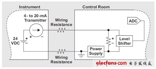
The 4-20 mA current loop signal is commonly used in industrial environments to enable remote measurement data transmission, such as processing temperatures or vessel pressures. This signal transmission method has become the first choice because it is simple, convenient, noise-resistant, safe, and can be transmitted over long distances without data corruption. These current loops are also low power systems due to the relatively low current flowing through the data. Previously, the power that was not used, or the power lost during signal transmission, was dissipated in the transmitter; but now, with modern integrated circuits, even this small portion of the power is saved to support the system. The required function works properly. 4-20mA current loop system basics Figure 1 shows a typical 4-20mA current loop system. A semi-regulated 24V DC power supply simultaneously supplies power to the current loop and transmitter components. The transmitter measures important signals (such as temperature, pressure, and other parameters) and then outputs a 2-20 mA current that is proportional to the strength of the signal. This current is transmitted through the line to a receiver system. After that, the current encounters a resistor forming voltage, which is read by an analog-to-digital converter (ADC) and then further processed. By connecting, the connection is returned to the voltage source that supplies the loop, thus forming a complete loop. Figure 1 Basic 4-20mA current loop system The use of these current loops in industrial applications has many benefits: The current loop is a simple circuit that requires only a simple power supply, a transmitter that performs the measurement and then generates a current, a transmission line, and a receiver circuit. The power supply only needs to provide a voltage sufficient to overcome various system voltage drop problems; the excess loop voltage is reduced at the transmitter. Since the current is low, there is only a small amount of power consumption, so there is less heat. l The current loop contains only one current loop. Therefore, according to Kirchhoff's current law, the current through all components in the loop is equal. This achieves high noise immunity, which is the key to industrial environmental applications. l Safety is achieved due to signal levels as low as 4 mA. If damage occurs inside the loop, or if the loop connection is broken, the receiver cannot read the current, indicating a fault, not the lowest signal level. As long as the supply voltage is high enough to overcome the system voltage drop, the ideal current representing the measured signal is maintained by the transmitter. Therefore, high voltage drop and low cost small gauge wires are used for interconnection, which only requires an increase in the supply voltage. Most importantly, the line allows for a relatively large voltage drop and a large number of wires can be used. In this way, physical isolation between the instrument under test and the control room that processes the measurement data provides protection for personnel in the control room. Basic system improvement We can use the extra loop voltage to power the receiver circuit, otherwise it will be dropped at the transmitter. Figure 2 shows a power supply inserted in the current loop. The power supply is placed in the control room along with its powered receiver circuitry - effectively converting the excess loop voltage to useful output power. Figure 2 Utilization of excess loop voltage in a 4-20 mA current loop Since the receiver resistance is no longer grounded, a level shifting circuit may be required to connect to the data converter input. This extremely simple circuit is available from any high-end shunt monitor (eg TI INA138, etc.). These devices measure the small sense resistor voltage drop across the common-mode voltage, reducing the necessary voltage drop across the receiver's resistance. This allows more voltage to be used by the power supply, reducing energy waste. This power supply typically provides a regulated 3.3V output to power the level shifters, data converters, and all other low-power devices in the control room. For example, a microprocessor from the TI MSP430TM platform examines received data and makes decisions; low-power RF devices from the TI CC430 family wirelessly transmit data to other locations. Wireless transmitters are particularly useful if you do not need to purchase and install lines for particularly long current loops to achieve cost savings. The power consumption of these devices must be very low because of the limited amount of excess energy extracted from the current loop. Finally, this power supply must also work with such low-power supplies—minimum current 4mA and maximum current 20mA. Since the voltage generated by this current is the excess voltage of the loop, the power supply must accept a wide input voltage range and still provide a stable output. For this type of power supply, it is more difficult to start the system with a current limiting power supply. In general, higher output power is required during startup to charge the output capacitor while providing a startup current to the load. It is much higher than the amount consumed by the system during normal operation. If the power supply is to provide this high power during startup, its output power will exceed the amount provided by the current loop. If this happens, the voltage entering the power supply will continue to drop before the power is turned off. Thus, before re-turning on, its input voltage will rise again and the process will be repeated. When the power supply operates through this small input power, starting the oscillation is a problem we need to overcome.
Prototype PCB Assembly = Prototype Printed Circuit Board Assembly, which means the PCB Board quantity is not many and could be taken as prototype job. Normally, Prototype PCB assembly job will be done all by hand, or the small parts by machine and big parts by hand, or all parts by machine. After all parts placed on the PCB board, then it will go through re-flow soldering process. Zhongfeng would manufacture the prototype PCB boards follow the design file, source the components follow the BOM file and do the PCB Assembly job follow the assembly drawing and the pick&place file. After PCB assembly done, the components would be mounted on the PCB boards tightly and connected each other through the copper circuits. We call such board as PCBA board or prototype PCBA board.
Depends on the components assembly types, it have THT PCB assembly, SMT PCB Assembly , one sided SMT and THT PCB assembly, two sided SMT and THT PCB assembly.
Depends on the PCB type, it have Rigid PCB Assembly, Flex PCB Assembly and Flex-Rigid PCB Assembly.
Also we would call some PCB assembly types as Prototype PCB assembly, Mass PCB Assembly , Turnkey PCB Assembly, LED PCB Assembly and BGA PCB Assembly , etc.
With our 15years professional experience, we are available for all types of PCB assembly service from prototype to mass production, available for 01005, 0201, 0.3mm BGA, 0.3mm QFP.
PCB Assembly Capabilities
Quantity
1 pcs - 1,000,000 pcs
Assembly type
SMT, THT or Hybrid
Parts procurement
Full turnkey (ZhongFeng provide all components)
Partial turnkey ( Customer provide the main components and ZhongFeng provide the rest)
Kitted (Customer provide all components)
Component types
SMT 01005, 0201, BGA 0.3mm pitch, QFP 0.3mm pitch, etc.
Test
Visual Inspection, AOI, Custom testing, ICT, FCT, Test jig
PCB Assembly Products Show
PCB SMT Assembly Factory Show
Prototype PCB Assembly Prototype PCB Assembly,Quick Turn Prototype PCB Assembly,Prototype PCB Assembly Service,PCB Prototype Board Assembly ZhongFeng Electronic Technology Co., Limited , https://www.dopcba.com