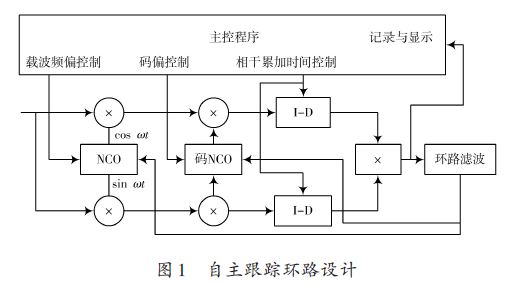
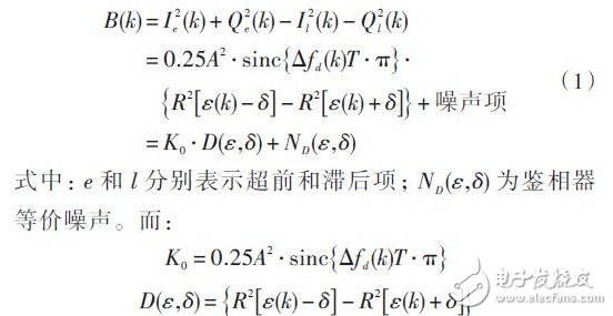
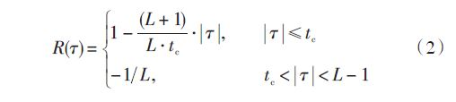
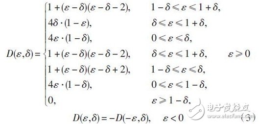
Abstract: Based on the GPS/BD compatible high-sensitivity navigation product development and industrialization project, the classic carrier tracking loop is modified to design a high-sensitivity tracking loop. The traditional single-point integral data is converted into a column of data, and after the FFT transformation of the data, the estimation accuracy of the carrier frequency can be improved, thereby improving the tracking sensitivity of the system. The simulation analysis of the high-sensitivity tracking loop demonstrates the ability of the highly sensitive tracking loop to track weak signals. 0 Preface The Global NavigaTIon Satel-lite System (GNSS) is of great importance in many fields, including politics, economy and military. From airplanes and automobiles to personal handheld communication terminals, GNSS positioning technology can be seen. The GNSS system is widely used in the civilian field and plays an important role in national economic construction. At present, there are four GNSS systems that have been used and developed in the world. The US GPS navigation system, the Russian GLONASS navigation system, the EU GALILEO navigation system and China's Beidou navigation system. With the advancement of technology and the increasing demand for applications, satellite navigation has the remarkable features of all-weather, automation, high efficiency, high precision, and its unique positioning navigation, precision measurement, timing and frequency calibration, etc. Involved in a large number of application areas, satellite navigation has become the world's third new IT economic growth point after cellular mobile communications and the Internet. With the full development of China's autonomous satellite navigation system Beidou system, the application of Beidou will be rapidly promoted, combining the various needs of satellite navigation and communication, multimedia and so on. For the navigation application of the mass and industry, the development of high-performance multi-mode high-sensitivity navigation baseband chip and multi-mode navigation baseband IP core will improve the technical level and market share of China's core navigation products, and provide independent core chips for major special demonstration projects. And solutions. The GPS signal power received by the antenna is generally -130 dBm, but in indoor, forest, urban and other complex environments, the GPS signal verification attenuation can reach 20~30 dB. At this time, the normal GPS receiver cannot achieve correct capture and tracking. This paper is based on the research background of high-sensitivity digital baseband chip. The classic carrier tracking loop is modified to design a high-sensitivity tracking loop design. The highly sensitive tracking loop receiver achieves correct capture and tracking. 1 Autonomous tracking loop design 1.1 Autonomous tracking loop design The satellite signal consists of three parts: a navigation message, a pseudo-random spread spectrum (C/A) code, and a carrier. The baseband signal processor synchronization process includes capture and tracking. Acquisition is a two-dimensional search process that roughly estimates the carrier Doppler shift and the C/A code phase offset caused by the relative motion of the satellite and receiver. These two parameters are used to initialize the tracking loop after the capture is completed. The tracking loop is accurately phase-synchronized and tracked, thereby achieving carrier stripping and C/A code stripping, and finally obtaining a navigation message for navigation solution. The satellite number and the spreading code phase in the results obtained by the autonomous acquisition channel are input to the satellite spreading code generator, and the generation of the spreading code sequence is started, including the leading 0.5 chip, the real chip and the hysteresis 0.5 chip. The path sequence is then correlated with the local pseudo code signal, and the operation of the tracking loop and the carrier tracking loop is tracked by the spreading code to keep the carrier loop and the code loop locked. The program structure is shown in Figure 1. The tracking loop includes a carrier tracking loop and a code tracking loop. The two loops interact with each other. Only when two loops are locked at the same time can the navigation message be demodulated. The carrier tracking loop is more sensitive to environmental noise, phase noise and dynamic stress of the crystal oscillator, and is more susceptible to loss of lock than the code tracking loop, thus becoming a key and design difficulty for the receiver. 1.2 code tracking loop Since the code tracking loop DDLL algorithm can be implemented in software, the pseudo code delay can be guaranteed to be accurate to 1% of chips. Therefore, the autonomous code tracking loop adopts this method for pseudo-code phase tracking, that is, the phase advance and lag signals are generated by the local code generator and correlated with the input signal, and the two branch results are compared to obtain the code phase error signal to control. The code DCO generates a local code signal that is in phase with the input code. The input of the code ring phase detector is the correlation signal of the phase/lead phase of the in-phase/quadrature tributary code. When the code correlation occurs, the loop enters the tracking state. Assuming d = 2δ, d is the phase interval between the phase lead and the lag branch, then the control quantity B(k) of the leading lag type non-coherent DDLL ring can be obtained by equation (1). : The gain coefficient and phase discrimination characteristic function of the phase detector are respectively indicated. The code length of the GPS C/A code is L = 1 023, the code length of the BD C/A code is L = 2 046, and the symbol width is tc = 20 ms. The correlation function is: The phase-detection characteristic function of the phase detector can be obtained: The phase discrimination characteristic function is a function of the correlation interval and code phase deviation. If the definition (-δ, δ) is the phase-detecting linear range, the slope D'(ε, δ) of the phase-detection property function at ε = 0 is the phase-detection gain of the DDLL ring, and Dmax (ε, δ) is the tracking traction range. . This Automation curtain is specially designed for automation industry. SDKELI LSC2 light curtain is designed for automation field, with small size, compact structure and strong anti-interference ability, and the product meets IEC 61496-2 standards. The Automatic Light Curtain is with reliable quality and very competitive price. It has been used in many factories and has replaced curtains from Sick, Omron, Banner, Keyence, etc. Automatic Light Curtain,Laser Light Curtain,Automation Light Beam Sensor,Automatic Infrared Beam Sensor,Infrared Beam Curttain Sensor,Infrared Beam Sensor Jining KeLi Photoelectronic Industrial Co.,Ltd , https://www.sdkelien.com