Manufacturing method of simple electronic pulse meter In order to facilitate frequent carrying and production, this machine only uses a CMOS integrated circuit and a triode. The quiescent current is only 10 ~ 20μA, and the electrode consumption is small, so only two AG10 button batteries are used in the whole machine. amplifying circuit: Shaping circuit: Audio and LED drive circuit: In addition to the circuit part of the electronic pulse meter, the quality of the sensor will directly affect the sensitivity of the instrument, so the production of the sensor is a very important part. As shown in Figure 2 (a), the ceramic side of the piezoelectric ceramic sheet is welded to the copper ring side (three points are evenly welded on the circumference), a thin shielded wire is used as the lead line, and the outer skin is connected to the copper ring , The core wire is welded to the ceramic surface through the copper ring gap. Weld a copper piece under the copper ring, as shown in Figure 2 (b). Finally, according to the thickness of the fingers of ordinary people, a piece of metal watch with a spring is intercepted and connected with the sensor, forming a circle, so that it can be worn on the finger when used, see Figure 2 (c). The model of the piezoelectric ceramic chip used for the sensor is HTD-20, but the following requirements should be noted when selecting the piezoelectric ceramic chip: connect the silver-plated ceramic layer to the Y-axis input end of the oscilloscope, the metal substrate ground, and touch the metal substrate by hand On one side, the output on the side where the silver plating is observed should be a positive pulse before it can be used. The electronic pulse meter takes out the "finger pulse" signal from the finger, which is very convenient to use. When the front end of the finger is slightly wrapped, you can feel a relaxed feeling under the effect of blood pressure on the front end of the finger. This signal is extracted by the sensor, converted into an electrical signal, and then displayed in the form of light and sound. Know the pulse beat. MLF is fully capable of providing high-quality AC adapter with the power arrange from 3W to 120W .All of them meet the worldwide safety and EMC standards as UL FCC CE GS BS CCC SAA, KC, PSE etc , and comply with the latest Rohs &Reach also. The AC adapter widly use in the field of telecommunications, audio/veido products ,IT & computer peripherals ,home appliances , LED lights ,toys ,and medical equipments .MLF has different designs to suit the conditions of the AC adapters used in various lines.and each power state there are several models for selection. meanwhile MLF also welcome OEM/ODM projects including customized AC adapters. DC Adapter,Usb Adapters,Wall Mount Adapters,Power Adapters,45W Series AC Adapter Meile Group Limited , https://www.hkmeile.com
The electrical schematic diagram of the electronic pulse meter is shown in Figure 1. It consists of sensor (B), amplifier, shaping circuit and driving circuit. The whole circuit is composed of 4 CMOS NAND gates to form the amplification, shaping and oscillation circuit. A sensor made of piezoelectric ceramics at the front end converts the pulsating pressure signal on the finger into an electrical signal. 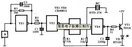
Because the electrical signal sent by the sensor is extremely weak, an amplifier circuit with high input impedance must be used. If the CMOS inverter is used as an analog device, as long as the appropriate linear bias is added, it is a high-impedance amplifier with good performance, such as YF1 in Figure 28-1. A resistor R5 is used to connect the input and output of the inverter YF1. It is both a feedback resistor and a bias resistor. This constitutes an amplifier with negative feedback. The function of capacitor C1 is to bypass high frequency to prevent self-oscillation.
The second stage uses inverter YF2 as a shaper. This stage works in the switching state, so the bias is added at the end. If the output level of YF1 is higher than the opening level of YF2, YF2 outputs a low level; if it is lower than the opening level of YF2, YF2 outputs a high level. Because the value of the feedback resistor R5 of the first-stage amplifier circuit is selected properly, the output of YF1 just exceeds the turn-on level of YF2. Once the sensor has a weak signal output, after YF1 is amplified, YF2 is shaped to output a high level. YF2 outputs low level when static.
YF3 and YF4 form a controlled multivibrator. When YF2 outputs a high level, the oscillator starts to oscillate. Adjust the resistance R1, R2 and capacitor C2, you can change the oscillation frequency. At the same time, YF3 drives the piezoelectric ceramic piece BC to emit sound, and YF4 connects the transistor VT1 to drive the light-emitting diode to emit light. 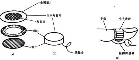
The electronic pulse meter does not have a power switch. When you use your finger to touch the sensor first, the instrument will emit a "chi, chi" sound, and the light-emitting tube emits red light, indicating that the instrument is working properly. Put the sensor on the finger as shown in Figure 2 (c) and feel a little pressure. It is better to wait for a while (because the blood flow of the finger needs to wait for a while before re-flooding into the finger), the instrument will jump with the pulse Sounds and displays red light.