Transistors are the basic devices in analog circuits. For electronic engineers, understanding the working conditions of transistors and judging the working state of transistors is very basic. This article will take you to learn or review. 1. Collector resistance Rc: In the common emitter voltage amplifier, in order to take out the amplified signal voltage Use (dynamic signal) at the output of the transistor, it is necessary to connect a resistor Rc in series with the collector. In this way, when the collector current Ic passes, a voltage drop IcRc is generated on Re, and the output voltage is taken out between the transistors ce, that is, Usc=Uce=Ec-IcRc, so Use also follows IcRc with the input voltage Ui. The occurrence of this changes accordingly. 2. Collector power supply Ec (or Vcc): Ec ensures that the collector junction of the transistor is reverse biased, allowing the tube to operate in an amplified state, making the weak signal a strong signal. The source of energy is based on the maintenance of Ec, not the transistor itself. 3. Base power supply Eb: In order to make the current amplification of the transistor, in addition to ensuring that the collector junction is reverse biased, the emitter junction must be forward biased. The function of Eb is to provide a forward bias voltage to the emitter junction with appropriate base. The resistor Rb is used to establish a certain static base current Ib. When Vbe is small, Ib=O, only when Vbe exceeds a certain value (about 0.5V for silicon tube, about 0.2V for cesium tube, called threshold voltage), the tube starts to conduct and Ib appears. Subsequently, Ib will increase as Vbe increases, but the relationship between Vbe and Ib is not linear: when Vbe is greater than 0.7V, Vbe adds a little more, and Ib increases a lot. The Vbe with the transistor fully turned on is approximately equal to a constant (about 0.5V for the silicon tube and about 0.5V for the xenon tube). 4. Base bias current resistor Rb: Under the condition that the size of the power source Eb has been determined, changing the resistance value of Rb can change the quiescent current Ib of the transistor, thereby changing the collector quiescent current Ic and the tube voltage drop Vce, so that the amplifier establishes a proper DC operating state. When the transistor operates in the amplification region, its emitter junction (between b and e poles) is positively biased, and the collector junction (between b and c poles) is reverse biased. For low-power NPN-type silicon, it is Vbe≈0.7V, Vbc “0V (specific value depends on the power supply voltage Ec and the value of the relevant component): For NPN-type manifold, Vbe≈0.2V, Vbc “0V; for For the PNP type transistor, the above voltage values ​​are opposite in sign, that is, the low power PNP type silicon tube Vbe≈-0.7V, Vbc"0V, for the low power PNP type manifold, Vbe≈-0.2V, Vbc"0V. If we find in the detection circuit that the inter-electrode voltage of the transistor is the above value, it can be judged that the triode operates in the amplification region, and the portion of the circuit composed of the triode is an amplifying circuit. In addition, in an oscillating circuit composed of a transistor, the triode also operates in the amplification region, but since the output of the triode is tuned to the b and C poles through the frequency selective resonant circuit and the phase is oscillated, then b, e The voltage Ube between the poles is less than 0.7V for silicon tubes (typically around 0.2V). If we detect Vbe "0.7V, and use a wire shorted to select the inductance in the resonant circuit to make the circuit stop Vbe0.7V, then the circuit can be judged to be an oscillating circuit. 2. The judgment of working in the deadline area: When the triode is operating in the cut-off region, both the emitter junction and the collector junction are reverse biased, and in actual circuits, the emitter junction can also be zero-biased. Thus, for low-power NPN-type transistors, Vbe ≤ 0, Vbc "0V (specific value is mainly determined by the power supply voltage Ec); for low-power NPN type transistors, Vbe ≥ OV, Vbc ≥ 0V, Vce≈ at this time Ec, if we detect the voltage between the transistors in the circuit, we can judge that the transistor works in the cut-off area. 3. Judging the work in the saturation zone: When the triode works in the saturation region, its emitter junction and collector junction are both positively biased. For low-power NPN-type silicon tubes, Vbe is 0.7V (slightly larger than when operating in the amplification area), Vbc is 0V (not greater than Vbe); for low-power NPN-type manifolds, similarly Vbe≥ 0.2V (slightly larger than the value when working in the amplification area), Vbc OV (not greater than the value of Vbe). For PNP type transistors, the above voltage values ​​are opposite in sign, that is, low power PNP type silicon tube, Vbe ≥ -0.7V, Vb "0V (not less than Vbe value; low power PNP type 锗 tube, Vbe ≤ -2V, Vbc "0V (not less than the value of Vbe). In general, at this time Vce ≈ 0.3V (silicon tube) or Vce ≈ 0.1V (锗 tube), if we detect the inter-electrode voltage of the transistor in the circuit meets the above In the case, it can be judged that the triode is operating in a saturation region. It should be pointed out that in some electronic circuits, such as switching circuits, digital circuits, etc., the triode works to switch between the cut-off area and the saturation area, as shown in the drawing. When point A is 0V, EB divides the base by a negative voltage through R1 and R2, and the emitter junction is reverse biased; at the same time, the collector junction is also reverse biased, then the transistor T is turned off; when the input of point A is 6V, R1 The R2 partial pressure causes the triode emitter junction to be forward biased, generating a sufficiently large base current to saturate the triode, and the output terminal L is about 0.3V. At this time, the collector junction is also positively biased. When we check whether the circuit is normal, we can input the voltage of 0V and 6V to the A terminal separately, and measure the voltage between the three poles in the two cases to see if the above cut-off and saturation conditions are met, so that the circuit can be judged to work. Is it normal? The transistor has three working areas, namely an amplification area, a cut-off area, and a saturation area. When designing the circuit, the transistor can be operated in different areas according to the requirements of the circuit to form an amplifying circuit, an oscillating circuit, a switching circuit, etc. If the triode changes the original normal working state for some reason, the circuit will malfunction; When the electronic product fails, it is necessary to analyze the fault. The first task is to check the working state of the triode as described above. For the specific detection work of the transistor, pay attention to two problems: First, it is better to use a digital multimeter with large internal resistance to reduce the measurement error, and avoid the change of the working state of the triode caused by the small internal resistance of the multimeter during direct measurement. Second, it is best to measure the voltage of each pole of the transistor to ground, and then calculate the value of Ube.Ubc or Uce to avoid the possibility of inducing circuit failure. KNL5-63 Residual Current Circuit Breaker
KNL5-63 Moulded Case Circuit Breaker is MCCB , How to select good Molded Case Circuit Breaker suppliers? Korlen electric is your first choice. All moulded Case Circuit Breakers pass the CE.CB.SEMKO.SIRIM etc. Certificates.
Moulded Case Circuit Breaker /MCCB can be used to distribute electric power and protect power equipment against overload and short-current, and can change the circuit and start motor infrequently. The application of Moulded Case Circuit Breaker /MCCB is industrial. KNL5-63 Molded Case Circuit Breaker,Small Size Molded Case Circuit Breaker,Electrical Molded Case Circuit Breaker,Automatic Molded Case Circuit Breaker Wenzhou Korlen Electric Appliances Co., Ltd. , https://www.zjmotorstarter.com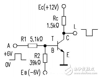
Korlen electric also provide Miniature Circuit Breaker /MCB. Residual Current Circuit Breaker /RCCB. RCBO. Led light and so on .