LED Chips: COB Bridgelux or Luminus.
12W LED Track Lights with international 2 phase, 3 phase, or 4 phase track connector.
CCT: warm white, natural white, cool white are available.
Function: Non-dimmable, dimmable and CCT changeable are available.
Types: DALI system, 0-10V systerm, Dial Switch, guide rail with power supply etc.
Beam Angle: High reflectance diffuser (Lens+Reflector) with 12° / 24°/ 36° for choice.
Dimension of 12W Led Track Lights: Φ70mm, 211*180mm
Finished Color: Matt White / Black / Silver etc.
High luminance flux: 900lm
High CRI: >90
Input voltage: AC110/220V 50/60Hz
Certification: CE RoHS
12W LED Track Lights 12W LED Track Lights, LED Track Light, 12W Dimmable LED Track Light SHENZHEN KEHEI LIGHTING TECHNOLOGY CO.LTD , https://www.keheiled.com
1 Main features of MCF5282 microprocessor
The MCF5282 microprocessor is the highest integrated ColdFire series 32-bit microprocessor launched by Motorola so far. It contains 2 KB of cache memory, 64 KB of random memory RAM and 512 KB of flash memory. The total number of I / 0 ports Reached 152. It also uses intelligent DigjtalDNA technology, the working speed is 59Dhrystone2.1 MIPS at 66 MHz. In addition, the MCF5282 microprocessor also has new equipment:
â—† Fast Ethernet Media Access Control (MAC), which supports 100 Mbps MII, 10 Mlaps MII and 10 Mbps 7-wire real interfaces, it expands the Ethernet connection from the board level to the chip level, which is different from other types of processors MCF5282 One of the features.
â—† QSPI module provides serial peripheral interface with serial transmission performance.
â—† 3 universal asynchronous serial interface modules UART.
â—† I2C system bus module.
â—† CAN 2. 0B standard interface module.
â—† 4 32-bit DMA timers / counters, 8 16-bit general timers / counters, 4 cycle interrupt timers / counters.
â—† 8-channel 10-bit A / D converter module (QADC).
â—† DMA control module can operate on 8-bit, 16-bit and 32-bit data.
â—† 2 interrupt control modules, each interrupt control module can manage 7 levels of interrupts, each level has 9 interrupt sources, a total of 126 interrupt sources can be managed.
â—† Reset control module with conflict detection.
â—† The power management module (PWW) has four operating modes: Run. Wait, Doze- and Stop.
2 Embedded main template of microcomputer protection device
2.1 The working principle of the microcomputer protection device The current and voltage signals sent by the system to be protected generate low voltage signals (within ± 10 V) after being transformed by the current and voltage transformers and sent to the main template. The MCF5282 microprocessor in the main template runs the on-chip protection software, samples the signal, and completes various numerical operations, analysis, and processing to determine the operating status of the system to be protected. If there is a fault, MCF5282 sends a trip action signal through the output template to achieve the purpose of protecting the system; at the same time, the protection action information is sent to the management template and the host computer by various communication methods to record, save data and alarm, and complete microcomputer protection The working process of the device.
2. 2 Embedded main template composed of MCF5282 In designing a 110 kV high voltage microcomputer protection device, the author chose to use MCF5282 as the core to form the main hardware template of the embedded system. It is mainly composed of data sampling, memory, digital input and output, communication, serial clock and E2PROM and other circuits, as shown in Figure 1. 
The connection and working principle of MCF5282 and each part will be described below.
2.2.1 MCF5282 circuit In order to improve the reliability of the main template, the peripheral devices of MCF5282 should be reduced as much as possible. MCF5282 is designed to operate in a monolithic mode. MCF5282 uses I / O ports or functional ports to exchange information with the outside. The reset circuit of the system adopts the reset circuit chip IMP706R with power supply monitoring. When the device is powered on, the power supply voltage is abnormal, the manual reset, and the program operation is confusing or overtime, the system can be reset when the "deadlock" occurs. The circuit is shown in Figure 2. . 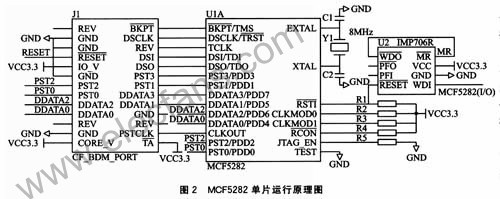
2.2.2 Memory and data sampling circuit The memory uses 2 pieces of FM18L08, and the data sampling uses AD976A. The data lines and address lines of the two devices are shared, and the control lines are shared with other lines except the chip selection line, as shown in Figure 3. The software in the MCF5282 microprocessor operates these signal lines as I / O ports. 
FM18L08 is a 32 KB non-volatile ferroelectric random access memory FRAM manufactured using advanced ferroelectric technology. Its data can be saved for 10 years after power down. Its high-speed write operations and the large number of erase and write cycles make it have higher advantages than other non-volatile memories. The connection of FMl8L08 and MCF5282 is shown in Figure 3. Two FMl8L08 are connected in parallel to form a 32 K × 16-bit memory. It can perform 8-bit and 16-bit data operations. MCF5282 has 64 KB of random memory on-chip, which is enough to store all kinds of data processed by software in the embedded system. The main purpose of expanding FM18L08 is to realize data recording and storage of action parameters.
There are 8 10-bit queue A / D converter modules (QAE) in MCF5282, but the number and accuracy of the channels cannot meet the requirements. Therefore, two 16-to-1 analog electronic switch chips MAX306 of the American letter company are used. AD976A constitutes a 31-channel 16-bit data acquisition circuit with a signal range of 10 V.
AD3976A is an analog-to-digital converter produced by Analog Devices. It has a resolution of 16 bits and a maximum sampling rate of 200 ksps. It is a successive approximation type analog-to-digital converter using charge redistribution technology. Its structure is simpler than that of a traditional approximation ADC. , And no longer need a complete analog-to-digital converter as the core. Because the capacitor network directly uses charge as a conversion parameter, and these capacitors have reached the role of sampling capacitors, there is no need to add a sample and hold, which greatly simplifies the front-end circuit. In the filter circuit, the AC and DC signals are filtered using traditional RC and RLC filter circuits.
2.2.3 Switch input and output circuit
MCF5282 main template has designed 34-channel digital input and 17-channel digital output. Each switch input passes through the optical isolation chip TLP521, and then reaches the I / O port of MCF5282. The control software sends the output signal from the I / 0 port of MCF5282, controls the relay in the output template through 74LVXC3245 and ULN2004 two-level drivers, as shown in Figure 4. 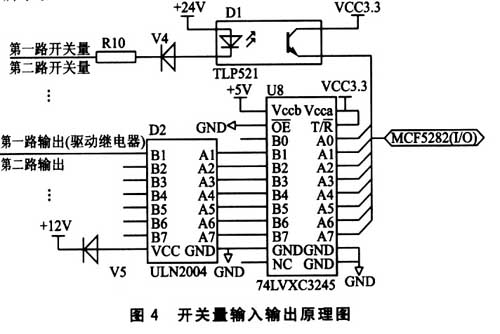
2.2.4 Communication circuit According to the communication port of the MCF5282 microprocessor, peripheral circuits for Ethernet, CAN, RS-232 and RS-485 communication are designed, forming a variety of communication methods to communicate information with the host computer system and management template. CAN, RS-232 and RS-485 communication transceivers use PCA82C250, MAX3232 and MAX485 respectively. In order to improve the communication quality, the photoelectric isolation device 6N137 is used for isolation. In order to meet the needs of high-end users, Ethernet communication is designed, and the peripheral driver chip selects the VT6103 chip.
2.2.5 Serial clock and E2PROM circuit The author chooses one piece of I2C bus interface clock chip PCF8563 and one piece of I2C bus interface memory chip 24LC256, which are all connected to the 12C bus of MCF5282 microprocessor, as shown in Figure 5. PCF8563 is an industrial-grade real-time clock chip designed and produced by Phlips. It has the characteristics of low power consumption and high precision, so that the hardware main template of the embedded system has a stable time signal for a long period of time. 24LC256 is a 256. The serial E2PROM of KB can be erased electrically. The main function is to store the important parameters required by the software of the embedded system during the operation, such as the protection settings. 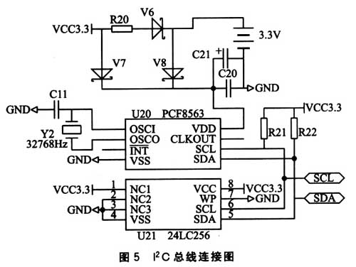
3 software implementation The overall structure of the software program mainly includes the main program, sampling interrupt service program and fault handling program. Normally run the main program, sampling 24 points per cycle (sine wave), interrupt the service routine every time the sample is executed and determine whether the starting element DIl of the phase current difference abrupt quantity acts. If DI1 is inactive, after the sampling and interruption program is executed, it returns to the main program normally; if DI1 is operating and after the sampling and interruption program is executed, it transfers to the execution of the fault handling program and completes the corresponding protection function, until the entire group returns to the normal main program. The program flow is shown in Figure 6. 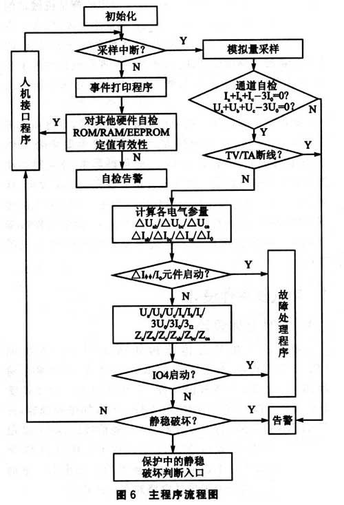
4 Summary This article introduces the main module of the embedded protection device using the microprocessor MCF5282 and its connection with peripheral circuits. Because the sampling circuit in this module is multi-channel high-speed sampling, the reference voltage VREF should be designed reasonably. When designing the PCB board, pay attention to a reasonable layout and set up a good electrostatic shield to prevent electromagnetic interference problems. In addition, in the digital input, output control and various control signal lines, the MCF5282 processor can be flexibly selected according to the distance of the PCB wiring. The embedded main template of the above design plus other templates can be configured as a microcomputer protection device with bus protection, line protection, generator protection and transformer protection functions. This protection device has been used in actual power monitoring (110V), such as generator sets, substations and railway lines, and the operation effect is good.


Application of MCF5282 microprocessor in power control system
This article will introduce a new type of embedded microprocessor MCF5282 and the embedded main template designed by it, which can meet the requirements of multiple communication methods, and its processing speed and the accuracy of implementing multi-channel AC and DC sampling are more Similar chips are much higher, and their real-time performance is more perfect.