Coupletetch Co., Ltd. supplies optomechanical product line, including Optical Mount, Crystal Mount, construction components, mechanical devices with electronics. These optomechanical components can be assembled to perform a specific function. Standard components such as posts, rails, translation stages, optic mounts, crystal mounts and BBO Pockels Cell holder are available.
Especially Mirror Mounts, Kinematic Mounts, Fixed optic Mounts, Rotation Mount and Component Mounts are matching our Optical Crystal and EO Q-Switch products.
Crystal Mount,Mirror Framed Mirror,White Round Mirror,Mirror Mount Coupletech Co., Ltd. , https://www.coupletech.com
Since there is no commutator (ie, brush) in PMSM, motor control technology must be based on knowledge of rotor position. The location must be measurable or estimable. Measuring the position of the rotor requires the installation of optical encoders (sensors) and other equipment on the motor shaft, which will greatly increase the system cost. If an effective method can be used to estimate the rotor position, then the sensor can be eliminated. There are many methods for estimating the position of the rotor, depending on the operating state of the motor (zero speed, low speed, high speed, etc.). When the motor is running at high speed, you can use the observer to obtain good results in terms of low-angle error, dynamic performance, and error filtering. The solution described in this article uses a "back EMF observer", which is based on the mathematical model of the motor.
The high-performance technology used to drive PMSM is based on field-oriented control (FOC), sometimes simply referred to as "vector control." The purpose of this method is to be able to independently control the motor torque and flux linkage in the air gap in a manner that accurately tracks the command trajectory regardless of changes in mechanical load torque and other disturbances, and achieve the fastest possible instantaneous response. The FOC method, coupled with a back-EMF observer to estimate the rotor position, is an ideal solution for driving a PMSM-based dishwasher pump.
Dishwasher pump
Home appliance manufacturers have recently started to use PMSM to drive dishwasher water pumps. Typical parameters include:
– Line voltage of 230V (Europe)
– 6 or 8 poles – 80W rated power – The relationship between the stator phase equivalent inductance Ld and Lq under the d and q axes is -Ld = Lq
The dishwasher water pump control algorithm operates in a closed current and speed loop. The water pressure in the dishwasher is represented by the physical design of the hydraulic system (water pipe, sprinkler, etc.), which can be controlled by changing the speed of the water pump.
Typical dishwasher pump operating characteristics include a water pressure range of 103 kPa (15 psi) to 827 kPa (120 psi) and a mechanical pump speed of 1,500 rpm to 3,500 rpm.
PMSM motor control method
There are several suitable control methods for driving PMSM. According to application performance and cost requirements, the vector control method (also called FOC) described in this section is more appropriate. The basic principle of the FOC control method is described in Figure 1. 
Figure 1: Principle of FOC control method
The necessary information for the vector control method includes the position and speed of the rotor, and the position of the magnetizing flux linkage of the motor. Traditional motion control systems use resolvers or encoders. In this way, the sensors, wiring and connectors required to monitor the rotor increase system cost and reduce reliability. For cost-sensitive applications, the rotor position must be obtained in other ways. Algorithms that do not use position sensors are called "sensorless control" methods. The block diagram in Figure 2 shows the sensorless vector control algorithm implemented. The position and speed are estimated using back-EMF observer and tracking observer, as shown in the figure.
Figure 2: PMSM vector control algorithm block diagram
The motor is a dynamic system, so we describe it with a set of differential equations. The stator voltage equation in the alpha / beta static reference frame can be expressed as follows: 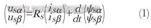

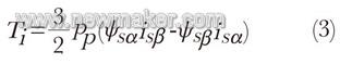
The mathematical model describes the behavior of the PMSM used in the dishwasher pump application, so it can be used in back-EMF observers.
Rotor position and speed estimation
In general, "esTImator" is a dynamic system that estimates state variables. The implementation of esTImator basically has two forms: open loop and closed loop. In the case of closed-loop esTImator, the error between the estimated value and the actual state variable is used as a correction term to adjust the response. The closed-loop esTImator is also called an observer.
The back-EMF observer is based on the estimation of electromotive force. The back-EMF model includes the induced voltage from the conventional back-EMF (rotor magnet) and the induced voltage from the stator inductance. This allows us to estimate the rotor position by estimating the back EMF. This method has certain limitations at low speeds because the back EMF signal is very weak, almost zero, and the observer diverges. When the minimum calculation speed required for effective estimation is reached, the back EMF observer estimates the rotor position, which can be used as the feedback signal of the vector control algorithm. The minimum calculation speed (voltage) threshold for correct observer calculation depends on the motor construction, and must be calculated based on the motor parameters or tested directly on the motor.
Observer algorithm processing derives the following equations from the PMSM mathematical model: 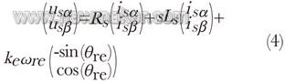
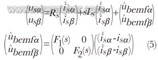
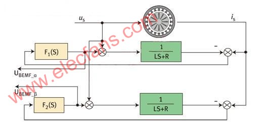
Figure 3: Block diagram of the back-EMF observer  )with(
  ). These two signals generate information about the position of the rotor. The electrical position of the rotor, converted to the rotor shaft angle, can be determined by the arc tangent function of the two inputs from the extended back-EMF estimation. This method produces unfiltered values ​​for rotor angle and no speed information.
Another widely used method for estimating rotor position and speed is the well-known angle tracking observer. By using an angle tracking observer, the noise of position estimation can be filtered out. Another advantage of the angle tracking observer algorithm is that it also estimates the rotor speed as part of the algorithm. Figure 4 describes the structure of the angle tracking observer. 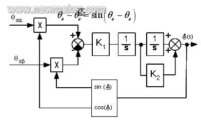
Figure 4: Block diagram of the angle tracking observer
The vector control method based on back EMF observer and angle tracking observer with rotor position and speed estimation algorithm has been realized by Freescale's MC56F8006.
There are three control loops to control speed, torque, and flux linkage. The control algorithm is executed in the priority interrupt service routine. The internal control loop is the most critical (q-axis current and d-axis current) and is executed every 125 μs. The external control loop (speed) is executed every 1ms. The internal control loop is uninterruptible, which can be ensured by assigning it an appropriate high interrupt priority. This method simplifies the design of the application framework and allows interrupt program priorities to be automatically managed by the processor. The vector control algorithm processes the following analog signals:
– Three motor phase currents (ia, ib, ic). These signals are measured by three parallel resistors installed at the bottom of the three inverter circuits.
– DC bus voltage.
In any given example, only two of the three phase currents are measured and the third is calculated. When the corresponding bottom transistor is turned on, the current can be seen on the parallel resistor. The window in which the current can be measured depends on the duty cycle of the generated PWM control signal, so the ADC conversion process needs to be started at an appropriate and precise moment. With the specially designed hardware in the MC56F8006 DSC, this difficult task can be successfully completed. The configurable synchronization pulse generated by the PWM module can be input into the programmable delay block (PDB). After that, the synchronization pulse is processed by the PDB module, and the output directly triggers the ADC module to achieve precise synchronization control of the ADC measurement. This synchronization mechanism is handled by hardware without any software intervention. The software only needs to read the ADC result register. The application described here uses this function to convert 6 analog signals every 125 μs. The ADC module contains two independent 12-bit ADC converters, which can be run sequentially, simultaneously or in parallel after being configured. To sample the phase current, use the simultaneous operation mode to make ADC measurements on both phases simultaneously. In this way, an accurate instantaneous measurement is achieved, and all three phase currents can be extracted from the measurement.
Since the back-EMF observer does not start from zero speed, the rotor is calibrated by driving the motor to a known state (phase), so we know the initial rotor position. Then an open loop start algorithm is used to accelerate the motor to the speed at which the back EMF observer can provide accurate feedback results. The switch from open-loop start to closed-loop control proceeds smoothly.
The operation diagram of the dishwasher pump solution is shown in Figure 5, and the inverter based on Freescale MC56F8006 is shown in Figure 6. 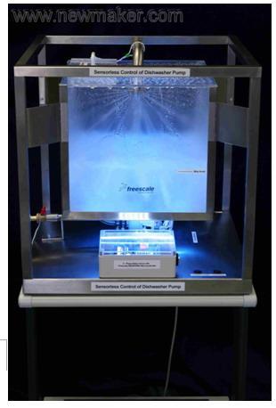
Figure 5: Running the dishwasher pump demo 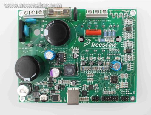
Figure 6: Three-phase inverter using Freescale MC56F8006 devices


Sensorless PMSM drive design of dishwasher pump
At present, the drive part of many dishwasher water pumps uses a three-phase permanent magnet synchronous motor (PMSM). PMSM requires an intelligent drive system, which contains a microcontroller to resolve the rotor position and implement a control loop to drive the motor to rotate. The new type of dishwasher controlled by the microprocessor can save more water and electricity while being more silent.