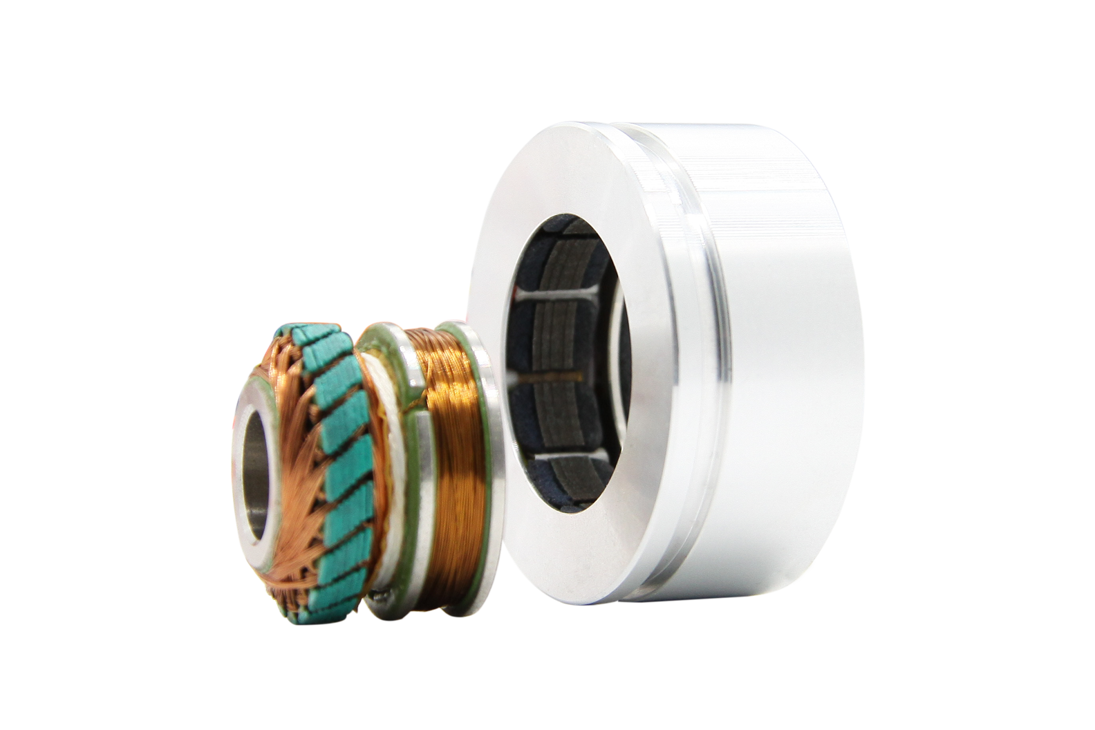
Resolver is a kind of commonly used angle detection component, because of its simple structure, reliable operation, and its accuracy can meet the general detection requirements
Resolver,Encoder Troubleshooting Resolver,Custom Resolver,Online Resolver Yuheng Optics Co., Ltd.(Changchun) , https://www.yuhengcoder.com
The automatic pressure controller of the atmospheric pressure boiler introduced in this example can automatically start the pump when the water temperature in the boiler reaches 85C, and automatically shut off the pump when the water temperature drops to 5O °C.
Circuit Operation Principle The automatic pressure controller circuit of the atmospheric pressure boiler consists of a power supply circuit, a temperature detection control circuit, a trigger, a working state indicating circuit and a control execution circuit, as shown in Figure 8-154. 
The temperature detection control circuit is composed of a temperature Sensor RT, resistors Rl-R5, potentiometers RP1, RP2, and an operational amplifier integrated circuit ICl (N1, N2).
The flip-flop is composed of NAND gates D1-D4 inside the four-NAND gate integrated circuit IC2.
The control execution circuit is composed of a resistor R7, a transistor V, a diode VD, and a relay K.
The working state indicating circuit is composed of a current limiting resistor R6 and a light emitting diode VL.
The power circuit is composed of a power switch S, a power transformer T, a rectifier bridge stack UR, a three-terminal voltage regulator integrated circuit IC3, and filter capacitors CI and C2.
Turn on the power switch S, after the AC 220V voltage is stepped down by T, UR rectified, Cl filtered and IC3 regulated, generate +5V voltage across C2, and supply temperature detection control circuit, trigger and control execution circuit.
The temperature sensor RT and the resistor R1 constitute a temperature detecting circuit; the potentiometer RP1 and the resistors R2 and R3 constitute a temperature lower limit setting circuit; RP2 and R4, R5 constitute a temperature upper limit setting circuit.
Adjusting the resistance of RPl, the voltage of point A (the positive phase input terminal of operational amplifier Nl) can be changed between 1.74 and 2.29V; adjusting the resistance of RP2 can make the voltage of point B (oppressing amplifier N2 inverting the big end) Change between 2.53-3V.
The resistance of the temperature sensor RT decreases as the temperature increases. When the water temperature in the boiler exceeds the upper limit of the set water temperature (for example, 85 ° C), the voltage at point C (the inverting large end of Nl and the large end of N2) will be higher than the voltage at point B, and the output of N2 is high. Flat, make the output point D of the trigger become high level, V saturation is turned on, K is pulled in, its normally open contact is turned on, and the working power of the water pump is connected through the AC contactor (not shown in the circuit). The pump starts to run and the hot water begins to circulate. As the water temperature drops, the resistance of the RT gradually increases, causing the voltage at point C to gradually decrease. When the water temperature is lower than the lower limit of the set temperature (for example, 5O °C), the voltage at point C will be lower than the voltage at point A, and Nl will output a high level, so that point D becomes low level, V is cut off, K is released, and the pump is released. Stop running.
When the pump starts running, VL lights up; when the pump stops working, VL goes out.
Component selection
Rl-R7 uses 1/4W carbon film resistor or metal film resistor.
Both RPl and R-Tu are selected linear potentiometers.
RT uses NTC type negative temperature coefficient thermistor (normal temperature value is 5kn).
Both Cl and C2 are aluminum electrolytic capacitors with a withstand voltage of 16V.
VD uses the IN4148 silicon switching diode.
VL selects φ3mm or φ5mm LEDs.
UR uses 2A, 5OV rectifier bridge stack.
V selects S805O or C8050, 3DG8050 type silicon NPN transistor.
lCl selects LM324 type four operational amplifier integrated circuit; lC2 selects CD401l or CC4011 type four NAND gate integrated circuit; IC3 selects LM7805 type three-terminal integrated voltage regulator.
T selects 3-5W, the secondary voltage is gV power transformer.
K selects JVX-l4FF or 4098 series 5V DC relay. 