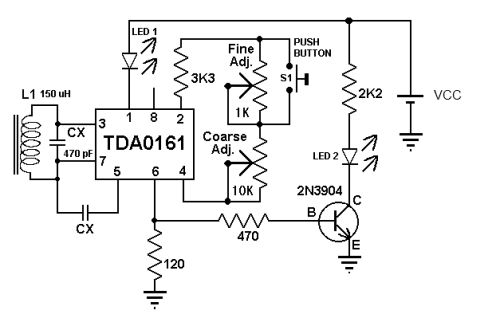
Based on the TDA0161 monolithic integrated circuit design metal body detection by detecting high frequency eddy current loss changes, these metal detector circuit diagrams. For probing metal, the TDA0161 requires an external LC tuning circuit. The output signal is a change in the supply current. This current is independent of the supply voltage and is either high or low or lacks a close metal object. The metal detector circuit uses two LEDs to provide a visual indication of the presence or absence of a metal coil. To adjust the circuit you need to make sure there are no metal coils nearby, then set the "middle position" to fine tune. After that, you need to adjust the adjustment of the course, turn on the LED, and adjust the trim to turn off the LED. The electronic circuitry of this detector operates over a wide range of input voltages of 4 - 35 volts. If you want, you can use other values ​​for CX capacitors and L1 inductors (changing this value will affect the oscillation frequency and detection range). include Coin Deposit Module and Banknote Deposit Module banknote deposit module coin deposit module support OEM,Deposit Module,Cash Deposit Module Suzhou Ribao Technology Co. Ltd. , https://www.ribaoeurope.com