One of the main challenges in communication system design is how to successfully capture high-fidelity signals. To avoid strong interference effects, signal distortion, and reduced sensitivity, cellular communication systems must meet the stringent requirements of cellular standards, such as code division multiple access (CDMA) and broadband CDMA (W-) with high dynamic range, high input linearity, and low noise. CDMA). In the past, some practical issues often led to the performance advantages of fully differential signal chains being overshadowed by single-ended signal chains, but with the continuous development of integrated RF circuit technology and high-performance differential RF building blocks, differential architectures can now be applied to high-performance reception Machine design. This article will discuss the performance and advantages of differential signal chains in 3G and 4G wireless applications. Receiver signal chain Figure 1 is the topology of a traditional superheterodyne receiver, which describes the advantages of a differential signal chain over a single-ended signal chain. Regardless of the topology used, our goal is to successfully send the required signals to the ADC for digital conversion. The signal path consists of the following RF modules: antenna, filter, low noise amplifier (LNA), mixer, ADC driver amplifier, and ADC. The LNA is the first module after the antenna and is used to amplify the signal above the thermal noise. The noise in this stage of the circuit is very important, because it will determine the system sensitivity, and amplification can ensure that subsequent mixers and amplifiers will not add significant noise. Along the signal path is a band-pass filter, used to suppress out-of-band signals and reduce distortion and noise caused by other circuit stages. Following the LNA, the mixer frequency converts the signal of interest and down-converts the high-frequency radio frequency signal to a lower-frequency, easier-to-manage intermediate frequency signal (IF). The ADC driver amplifier and anti-aliasing filter (AAF) pre-process the signal to be digitized. The driver provides gain, and AAF suppresses signals outside the first Nyquist zone, including noise and out-of-band spurious components that will be sent to the ADC. At the end of the analog signal path, the ADC completes the digital conversion of the baseband information. Ideally, only the signal of interest (the blue graph on the left in Figure 1) will be transmitted to the digital domain. A robust system needs to be used to process this potentially small target signal while suppressing potentially large interfering signals. Robust system design requires high sensitivity, input linearity, selectivity, and noise immunity. Depending on the specific application and architecture, performance indicators may change, but in most communication systems, distortion, noise floor, and dynamic range are factors that are usually considered. The input third-order intercept point (IP3) and 1dB compression point (P1dB) must be high. Other factors to consider include low cost, low power consumption and small size. Differential advantage Figure 2 compares the basic differences between single-ended and differential signals. A common gain block is used here, but the same concept can be applied to mixers and other devices in the signal chain. When comparing single-ended and differential signals, keep system-level performance evaluation standards in mind to achieve a good overall receiver design. By definition, a single-ended signal is an unbalanced signal, measured by the difference between the signal of interest and a fixed reference point. This reference point is usually ground and is used as the return path of the signal. If an error source is introduced into the signal path, problems will arise. Because the ground reference is not affected by the injection error, the error will be transmitted forward through the signal. Without extremely complex cancellation techniques, any signal changes introduced in a single-ended configuration are difficult to eliminate. Therefore, single-ended signals are easily affected by noise and electromagnetic coupling interference. On the other hand, the differential signal consists of a pair of balanced signals, which are centered at the reference point, with the same amplitude and opposite phase. The difference between the positive and negative balanced signals corresponds to the composite differential signal. If the error is introduced into the differential system path, it will increase to two balanced signals at the same amplitude. Because the return path is not a fixed reference point, the error will cancel out in the differential signal. Therefore, the differential signal chain is not susceptible to noise and interference. This inherent error cancellation function can also provide better common mode rejection ratio (CMRR) and power supply rejection ratio (PSSR). Differential signal chains also have an advantage that single-ended signal chains do not have. That is, the composite signal swing can reach twice the single-ended swing at the same power supply voltage, thereby increasing the signal-to-noise ratio. In other words, the amplifier margin is increased at the same power supply voltage and the distortion is reduced; or a lower power supply voltage can be used to provide the same signal swing, thereby reducing power consumption. Figure 2 shows the even harmonic cancellation inherent in differential systems. Non-linear devices, such as the single-ended and differential amplifiers in this example, can be described by the power series expansion transfer function given a sinusoidal input signal. In the single-ended scheme, each frequency-doubled component of the output has a constant, including even and odd frequencies. In the differential module, even-order nonlinearity is canceled out in the composite output response. Although actual devices cannot achieve perfect cancellation, they do benefit from the reduction of even harmonics. Figure 3 shows the harmonic distortion of an ultra-low distortion, low-noise differential amplifier optimized for driving high-speed 8-bit to 16-bit ADCs. The figure shows the second and third harmonics when the ADC device is configured for single-ended and differential topologies. Although the distortion in single-ended mode is very low, the HD2 value at 100MHz is 82dBc, but the even-order performance when using differential operation is better, and the HD2 value is less than 100dBc at the same frequency point. Therefore, under the same power rail conditions, P1dB and IP3 of the entire signal chain using differential topology are expected to increase by about 6dB. Differential signal chain With the development of receivers, differential components have become more and more widely used, and they can provide higher performance levels. This evolution started with the ADC and gradually developed upstream in the signal chain. In the past, signal application issues and limited differential RF building blocks have led people to choose single-ended or partial differential signal chains. An example of a partial differential signal chain is to eliminate the differential ADC driver and replace the ADC with a single-ended device and amplifier. Although this is a simple solution, the constant pursuit of performance requires more upstream circuits to adopt a differential topology. In addition to consuming more power, single-ended driver amplifiers usually have worse even-order distortion, CMR, and PSR. As shown in Figure 1, the commonly used receiver architecture is single-ended RF input and differential output. The dividing line between single-ended and differential operation seems to be at the mixer, and RF components like LNA are still single-ended components. Most SAW filters and mixer cores are inherently differential circuits, but they are converted to single-ended mode according to the application purpose. For many years, double-balanced mixer topologies have been widely used in cellular equipment due to their high linearity. Unfortunately, the traditional transformer network used to couple the signal to the mixing core takes up a considerable amount of circuit board area, adding a lot of cost to the design. Newer RF components, such as the ADL535x mixer series, integrate baluns and transformers, and provide simple-to-use RF modules with single-ended RF inputs and differential IF outputs. Figure 4 shows that all three mixer ports are internally differential. For convenience, the RF and LO ports are connected to the outside using transformers, thus allowing single-ended interfaces. In contrast, the IF output port contains a driver amplifier with a 200Ω output impedance, and uses a differential method to facilitate connection with a differential SAW filter. The integration of the local oscillator and the RF balun limits the operating frequency of the mixer, so it is required to use a device series that works specifically in the cellular frequency range. EOC is a device for Ethernet transmission over coax featuring Coax to UTP connectivity, equipped with one Ethernet port and four BNC ports, which can make a ring or aggregation. So it can be used in pair or one to multi. Ethernet And Power Over Coax Converter Ethernet And Power Over Coax Converter,Coax To Ethernet,Coax To Ethernet Adapter,Ethernet To Coax Adapter,POE over Coaxial Extender Shenzhen N-net High-Tech Co.,Ltd , http://www.nnetswitch.com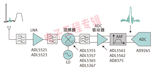
Figure 1: Receivers are constantly evolving, and more and more receivers will use differential components. This trend started with the ADC and will gradually move upstream in the signal chain. Advanced integrated RF circuit technology and expansion of differential RF building blocks allow differential architectures to be applied to high-performance receiver designs. 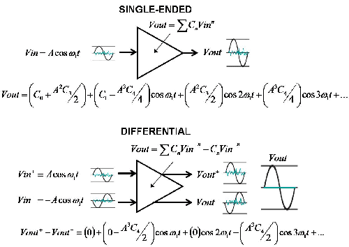
Figure 2: The inherent cancellation advantages of differential signals are resistant to noise and interference, while providing even harmonic cancellation. 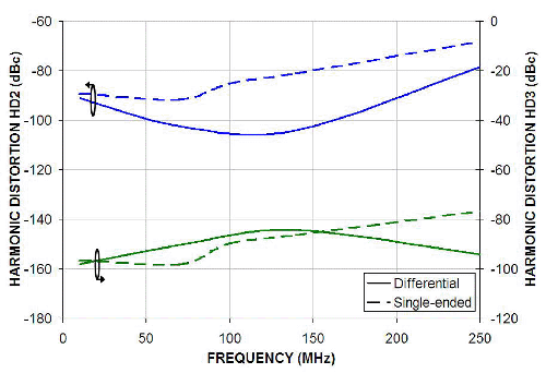
Figure 3: Although the distortion performance in single-ended mode is very low, differential operation does have significant benefits for even-order performance. Under the same power rail conditions, the differential topology output 1dB compression point and IP3 are expected to increase by about 6dB. 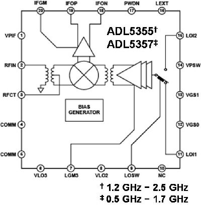
Figure 4: Recent developments in integrated RF circuit technology allow designers to easily use mixers with single-ended RF inputs to differential IF outputs. All three internal mixer ports can take full advantage of the differential, while at the same time being more easily connected to the outside world.
The equipment can transmit signal over all kinds of common cables such as telephone line, Ethernet cable, UTP or coax etc., with excellent isolation, thunder prevention and anti-jamming function. In the practical project, this device is proved to be of high performance in surge prevention. It transmits IP video or Ethernet up to 1.5km at a max rate 70Mbps over existing coax, thus cut the cost by avoid re-cabling when swapping analog cameras for IP/Megapixel models.
it can supply Power Over Ethernet cable for PD devices like HD cameras, wireless AP, IP telephone equipment. Our EOC support IEEE802.3af (15.4W) and IEEE802.3at (25.5W) standard.
EOC series also supports POC (Power over Coax) function. Model at local side (namely the master) can supply power over coax cable for the model at remote side (the slave) and IP cameras.