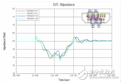
The characteristic impedance of a transmission line depends on its structure and material selection. Figure 1 is a street section of an HDMI cable, the typical structure of which is shown in Figure 2, which mainly includes a wire and a connector portion. Figure 1: HDMI cable (partial) Figure 2: HDMI cable head structure In order to ensure the characteristic impedance of the cable, it is first necessary to ensure that the characteristic impedance of the wire can be as close as possible to the target characteristic impedance. Figure 3 is a cross-sectional view of the wire used in the HDMI Type A/C cable. After the material is determined, the 2D field solver can be used to determine the characteristic impedance. The appropriate design parameters can be used to determine the design dimensions of the wire. Figure 3: Type A/C wire model A connector is a key structure in which a cable can be detachably connected. Due to the complicated structure of the connector, the impedance control is far less easy than the wire, so in the general industry specifications, the impedance matching specification of the connector section is slightly relaxed. Even so, for high-speed interconnected connectors, there are still significant challenges in controlling impedance. Figure 4 is the result of a characteristic impedance test of an HDMI cable. The result indicates that there is a large specific impedance deviation (out of specification) in the connector area, and there are some columns in which the characteristic impedance is too long. The problem. Figure 4: Characteristic impedance test results of a certain HDMI connector Through the three-dimensional high-frequency structural analysis, the scattering matrix in the connector section can be effectively predicted, and the basis for evaluating the high-frequency characteristics of the structure can be obtained. Similar to the mechanical evaluation of the structure, the high-frequency structural analysis also requires the following steps: first, establish the three-dimensional structure, then specify the high-frequency material characteristics of each part, and secondly, set the appropriate boundary conditions and background analysis, and finally The solution settings can be added and the high frequency analysis of the structure can be performed. Figure 5 shows the local effects of the model for high frequency structural analysis. Figure 5: HDMI cable to board connector high-frequency structural analysis model Through the high-frequency analysis of the structure, the scattering matrix or RLGC matrix of the structure can be obtained, and then the SPICE software can be used to analyze the time domain and the frequency domain (Fig. 6). The specific impedance can be obtained through specific operations and conversions. 7) Simulation results of various high frequency characteristics. Figure 7 HDMI connector characteristic impedance simulation results Medical Equipment, rechargeable batteries, battery charger, battery pack Ji'an Powercom New Energy Co., Ltd. , https://www.expowercome.com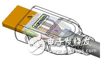
Figure 1: HDMI cable (partial) 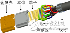

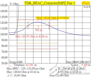
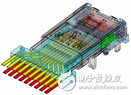
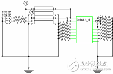
Figure 6 HDMI cable to board connector SPICE model