There is an effective passive way to suppress the ringing problem caused by energy leakage in a flyback transformer and clamp the overvoltage by implementing a recovery coil that is wound around the primary coil. This technique is commonly used for transformer demagnetization in forward converter configurations. In fact, this coil has a tight magnetic coupling with the primary coil, but in addition to controlling the leakage energy back to the power input, it is still technically a secondary coil. Therefore, it can also be used for other purposes, such as self-powering a PWM controller or converter.
DB25 Female Connector, DB25 Male Connector,DB9 Male Connector,DB9 Female Connector,DB9 Right Angle Backshell,Molded D-Sub Cables
The On-site injection molding enables us to custom mold your D-Sub assemblies to your specs with logos. We are tooled for:
DB9 molded cables,,DB25 molded cables, DB50 molded cables, HD15 molded cables
DB Backshell or Boot-Kit Cables: The backshell cans and boot-kits are available for D-Sub DB15 cablesD-Sub DB37 cables.
Backshells are offered for: D-Sub high-density HD26, HD44, HD62, HD78
D-sub cable, DB cable, 9pin DB cable, molded DB connector, Data Cable ETOP WIREHARNESS LIMITED , https://www.wireharness-assembling.com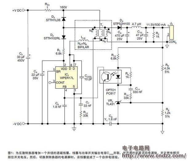 In Figure 1, there is a flyback converter that includes an additional recovery and self-powered coil NR that is wound with the primary coil NP and is implemented on a Viper17L modified verification board from STMicroelectronics. NS is the secondary coil and the residual leakage inductance is expressed as LLK. RS1 is a current sense resistor and R1 is a current limit resistor. The transformer ratio is the same as the original transformer.
 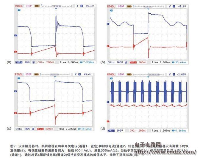 The output voltage (11.5V) is slightly lower than the original 12V to accommodate power rails as low as 145VDC. Figure 2a shows the primary current waveform of the original Viper17L structure with the power switching voltage and the damper disconnected. It can be seen that at full load (500 mA), on the 160 VDC power line, the ringing due to leakage inductance is approximately 540V peak. Figures 2b and 2c are the same waveforms in the case where the recovery coil is implemented as a damper and a self-powered coil. When the supply rail voltage is applied for the first time, the high voltage current generator implemented in Viper17 begins to charge capacitor C4 until the converter's VDD power-on threshold is reached and the PWM control is activated. The converter is then powered by the energy stored in capacitor C4. In the conduction phase, all diodes, D2, D3, and D4 are reverse biased. When the power switch is turned off, the magnetizing current flows into the recovery coil, turning D3 on, thus limiting the VDS to 2 x VDC. When the leakage energy is completely returned to the power input, D3 is reverse biased, and the recovery coil begins to discharge capacitor C4 through diode D2. The charging current cannot flow out of the power rail because D3 is biased off and the recovery coil provides power to the converter. The Viper17 is well-suited for low standby power consumption, such as it enters burst mode when no load is present, and internal circuitry is switched to a low-power state when idle. To maintain the burst mode, the circuit contains a 1kΩ preload resistor R2, which reduces the average switching frequency at no load, as shown in Figure 2d. In this way, the recovery coil can successfully maintain the operation of the converter under any load conditions, and at the same time, effectively clamp the power switch overvoltage caused by the flyback transformer leakage inductance.