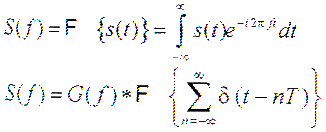
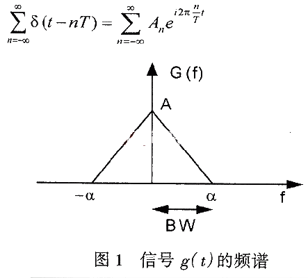
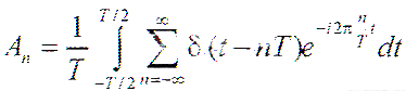
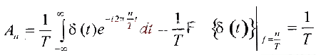
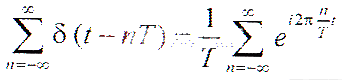
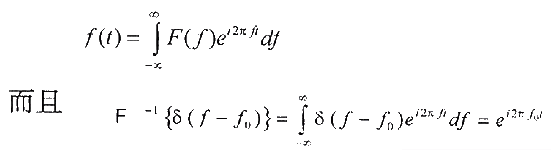
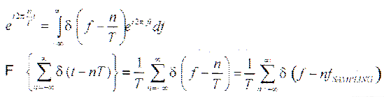
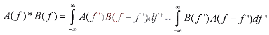
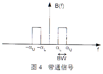
Sampling and aliasing analysis of limited bandwidth signals 1. INTRODUCTION More and more applications require sampling analog signals, converting them into digital signals, performing various calculations and processing on the digital signals, and then converting them into analog signals. This article discusses how to sample the analog signal and shape it to maintain the original signal. 2. Sampling and aliasing analysis of baseband signals are discussed first with a limited-bandwidth signal. A limited-bandwidth signal refers to a signal whose amplitude of all frequency components except a certain frequency point (cutoff frequency point) is 0. As shown in Figure 1, g (t), all spectral components in the frequency range greater than the cut-off frequency α are 0. In this case, α is the bandwidth of this baseband signal. The sampling of g (t) can be expressed mathematically in the following way: multiply g (t) by the impulse function with period T. The signal value of g (t) at the impulse point is sampled, while the values ​​at other points are all zero. From the analog signal point of view, it is to sample g (t) according to the frequency fSAMPLING = 1 / T. The sampled signal s (t) can be expressed by the following formula: In order to obtain the spectrum of the sampled signal s (t), the Fourier transform can be performed on s (t): The impulse string function is a periodic function, which can be expressed by Fourier series, as follows: The Fourier coefficients here are: The upper and lower limits of the integral in the above formula are only determined by one cycle. Under the premise of ensuring equivalence, the following transformation can be carried out: the integral in the above formula is replaced by a Fourier integral from negative infinity to positive infinity, and the periodic impulse function is replaced by the fundamental frequency impulse function, then the above formula can be rewritten as : The impulse string function can be expressed by the following simplified form of Fourier transform: Considering that a signal can be obtained by integrating its Fourier transform, as follows: The following final results can be obtained The convolution of the two signals A (f) and B (f) is defined as: Figure 3 shows the aliased sample signal. The high-frequency signal component fH is superimposed on the low-frequency part. When designing, a low-pass filter is usually used to restore the original spectrum and filter out other spectral components. When a low-pass filter with a cutoff frequency of α is used to recover the signal in Fig. 3, it cannot filter out the aliased high-frequency signal, resulting in signal degradation. 3 Sampling and aliasing analysis of the band-pass signal Let's look at another limited-bandwidth signal, the band-pass signal. The low-frequency cut-off point of the band-pass signal is not at 0Hz. The spectral energy range of the band-pass signal in Figure 4 is between αL and αU, and its bandwidth is defined as αU-αL. The main difference between a bandpass signal and a baseband signal is the definition of bandwidth. The bandwidth of the baseband signal is equal to its high frequency cutoff frequency, and the bandwidth of the bandpass signal is equal to the difference between the high frequency cutoff frequency and the low frequency cutoff frequency. From the previous discussion, we can see that the sampled signal repeats the frequency spectrum of the original signal in a 1 / T cycle. Because this spectrum actually includes a frequency band of 0 amplitude from 0 Hz to the low-frequency cutoff frequency of the original bandpass signal, the actual original bandpass signal bandwidth is smaller than αU. In this way, a certain frequency offset can be made in the frequency domain, and the sampling frequency can also be reduced. In order to satisfy Nyquist's law, an original bandpass signal with an actual bandwidth of αU / 2 can be set to αU. The frequency spectrum of the sampled signal is shown in Figure 5. Such sampling does not cause aliasing, so if there is an ideal band-pass filter, the original signal can be completely recovered. In this example, the difference between the baseband and bandpass signals is very important. For baseband signals, the bandwidth and corresponding sampling frequency are determined only by the high-frequency cutoff point. The bandwidth of the band-pass signal is usually smaller than the high-frequency cutoff frequency. 4. Sampling method and result analysis The above characteristics determine different methods for recovering the original signal from the sampled signal. For the baseband signal and the bandpass signal with the same high-frequency cutoff point, as long as a suitable bandpass filter is used, the sampling frequency of the bandpass signal can be reduced (the white rectangular part in Figure 5). The low-pass filter cannot recover the original signal in this case. As can be clearly seen from Figure 5, the shaded part is still included in the recovered signal spectrum. So if you want to use a low-pass filter to recover the bandpass signal in Figure 5, the sampling frequency must be above 2αU to avoid aliasing. The signal with limited bandwidth must be fully recovered under Nyquist's law. For band-pass signals, when using a band-pass filter, the Nyquist sampling frequency can be used to avoid aliasing. Otherwise, a higher sampling frequency must be used. This is very important when choosing ADC and DAC in practical applications. 5 Conclusion The above test results show that the sampling law is a basic tool for signal sampling applications, and strict mathematical analysis is also very important for the selection of parameters in the application. funcTIon ImgZoom (Id) // Re-set the image size to prevent the form from being broken {var w = $ (Id) .width; var m = 650; if (w <m) {return;} else {var h = $ (Id) .height; $ (Id) .height = parseInt (h * m / w); $ (Id) .width = m;}} window.onload = funcTIon () {var Imgs = $ ("content"). getElementsByTagName ( "img"); var i = 0; for (; i
The 20V series Dc Power Supply could be widely used for charging 12V battery system. It`s constant power and wide range of voltage and current output with accurate voltage and current measurement capability.
Our apm DC Power Supply inherits the functional design and maintains the high power density characteristic and 1U height appearance.Standard communication interface includes RS232/RS485/USB/LAN,GPIB is optional.Users can choose the Variable Dc Power Supply that fits their testing requirements perfectly.
Some features of the dc Power Supply as below:
20V Dc Power Supply,High Voltage Dc Power Supply,Variable Voltage Dc Power Supply,Power Supply APM Technologies (Dongguan) Co., Ltd , https://www.apmpowersupply.com
 Based on the above results, reconsidering the sampled fundamental frequency signal, its Fourier transform is:
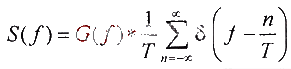
 Then S (f) can be rewritten as:
 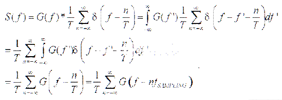 The above formula is the sampling law we often say. It shows that the signal sampled by period T in the time domain will repeat the frequency spectrum of the original signal at a frequency of 1 / T, as shown in Figure 2.
 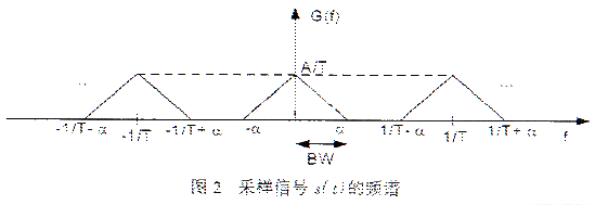 To preserve the information of all original signals, it must be ensured that no aliasing occurs between each repeated spectrum. Otherwise, it is impossible to recover the original signal from the sampled signal. Aliasing means that the high frequency band masks the low frequency signal, as shown in Figure 3. To avoid aliasing, the following conditions must be met: 1 / T ≥ 2α or 1 / T ≥ 2BW. The sampling frequency can also be expressed as: fSAMPLING ≥ 2BW The above indicates that the minimum sampling frequency that will not cause aliasing is 2BW. This is Nyquist's sampling law.
 It is also important to make assumptions about signals with limited bandwidth. Mathematically, a signal cannot be really limited in bandwidth. The Fourier transform law tells us that if a signal is finite in the time domain, its frequency spectrum will expand to infinity, and if its bandwidth is limited, it will be infinite in the time domain. Obviously, we cannot find a time domain signal with an infinite period, so it is impossible to have a truly limited bandwidth signal. However, the spectral energy of most actual signals is concentrated in a limited bandwidth, so the previous analysis is still valid for these signals. Sampling sinusoidal signals can be very simple and convenient to detect whether the sampling frequency is low, because the aliasing phenomenon is unique to the low sampling frequency. The (impulse string function) spike in the frequency spectrum of the sinusoidal signal only appears at the corresponding frequency point. When aliasing occurs, the spike will move to another frequency point, which corresponds to the aliased signal. The following test results were obtained using Maxim's latest 125Msps, 12-bit ADC: MAX1951. Figure 6 is its output signal spectrum, the corresponding input signal frequency fIN = 11.52884MHz. Obviously, the highest peak occurs exactly at this frequency. There are other small spikes in the spectrogram, which are caused by harmonics caused by the nonlinearity of the ADC, and are not related to the subject of this article. Since the sampling frequency fSAMPLE = 125MHz, which is much greater than twice the input signal frequency required by Nyquist's law, there is no aliasing. If the input frequency is increased to fIN = 183.458 MHz, which is greater than fSAMPLE / 2, there should be aliasing at this time. Figure 7 is the output spectrum when fIN> fSAMPLE / 2. The main peak falls at 58.48MHz, which is the aliased signal. In other words, a signal that was not included in the original signal appeared at 58.48MHz. In Fig. 6 and Fig. 7, only the spectrum below the Nyquist frequency is given. Because the spectrum is periodic, the display part of the figure already contains all the necessary information. Figure 6 and Figure 7