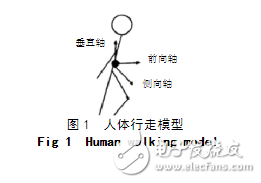
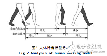
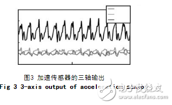
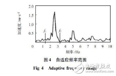
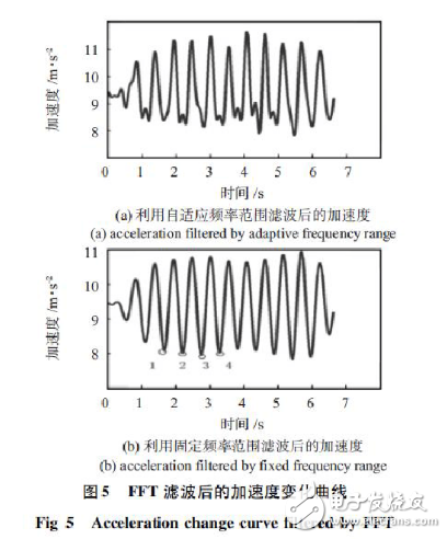
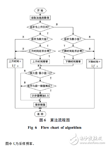
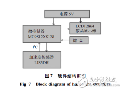
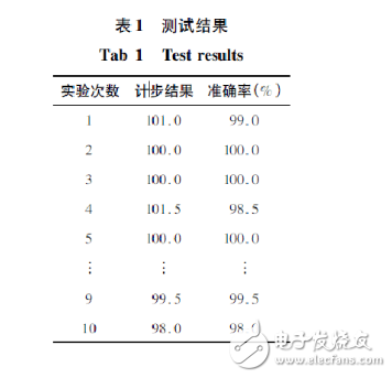
The pedometer is a daily exercise progress monitor that calculates the number of steps people walk, estimates walking distance, calories burned, and allows people to monitor their fitness intensity, exercise level and metabolism at any time. Early mechanical pedometers used the vibration generated by people to move to trigger the mechanical switch detection step. Although the cost was low, the accuracy and sensitivity were low, the volume was large, and it was not conducive to system integration. With the development of MEMS technology, inertial sensors based on MEMS technology have been rapidly developed. They are characterized by low price, small size, low power consumption and high precision. The electronic pedometer designed by MEMS accelerometer is used to measure the walking time of the human body. The acceleration information can overcome the shortcomings of the accuracy and sensitivity of the mechanical pedometer through the calculation of the software algorithm. It can accurately detect the pace, and can also output real-time data of the motion state, and collect and analyze the motion data. Extracting the characteristic parameters of human walking by gait acceleration signal is a simple and feasible gait analysis method. The walking motion consists of three components, which are forward, lateral and vertical, as shown in Figure 1. The LIS3DH is a three-axis (X, Y, Z-axis) digital output accelerometer that corresponds to the three directions of motion. The movement component of the walking motion at a step, that is, the step of acceleration in a step is shown in Figure 2. The ankle is off the ground is the beginning of a step. At this time, the vertical acceleration of the reaction force of the ground begins to increase, and the center of gravity of the body moves up. When the foot reaches the highest position, the vertical acceleration reaches the maximum, then the foot moves downward, and the vertical acceleration begins to decrease until the foot touches the ground, the acceleration is reduced to the minimum value, and then the next step occurs. The forward acceleration is generated by the friction between the foot and the ground. Therefore, the feet increase when they touch the ground and decrease when they are off the ground. Figure 3 shows the acceleration changes of the X, Y, and Z axes detected by LIS3DH in a walking experiment. It can be seen that the Z-axis acceleration data (vertical direction of human walking) has obvious periodicity, and the minimum acceleration value corresponds to the foot leaving the ground (the start or end of the step), and the maximum value corresponds to the highest point of the foot. In the specific use, the placement of the handheld device is arbitrary, and the three axes of the accelerometer may not coincide with the three axes defined by the human body model. The peak-to-peak value of the acceleration is used to judge the maximum acceleration output. The axis acts as an effective axis. However, this method is easy to lose the counting point, so that the counting is not accurate enough. In order to make full use of the three-axis signal output by the acceleration sensor, the acceleration signal is used for modulo summation and used for step counting. It can be seen from Fig. 3 that although the original output of the Z-direction accelerometer has a certain periodicity, the variation due to noise is complicated, and it is not easy to directly perform the step counting, and the signal needs to be filtered to eliminate the noise influence as much as possible. Normally, people's cadence will not exceed 5 steps / s at the fastest, and the slowest is 0.5 steps / s. Therefore, it can be considered that the frequency in the original signal is 0. The 5 to 5 Hz signal is a useful signal, and the other signals are noise. You can use (FFT) filtering to achieve the requirement to retain part of the frequency information and extract useful information. However, during any period of normal walking, the variation of the stride frequency will be concentrated in a small range near the peak frequency instead of 0. 5 ~ 5 Hz is so large, so this paper has analyzed a large amount of experimental data spectrum, established a ratio of 0. 5 ~ 5 Hz Small adaptive frequency range (f1, f2) (as shown in Figure 4), the useful signal in the frequency range is reserved by FFT, and the useless information outside the range is removed. It has been experimentally verified that the dynamic frequency range can better remove the influence of noise on the judgment of the number of steps, as shown in Fig. 5(a) and (b). Figure 5 (a) is the acceleration curve after filtering the original acceleration signal by FFT filtering and dynamic frequency range. Figure 5(b) is directly using FFT filtering and 0. Acceleration curve after filtering the original acceleration in the frequency range of 5 to 5 Hz. It can be seen from Fig. 5 that some of the noise in Fig. 5(a) can not be eliminated, and there are multiple peaks. In the step (5), the acceleration curve is smoother, and the periodicity of acceleration is very obvious. The law is also relatively simple. The software algorithm can be used to realize the step counting. Although there is still a certain output when the acceleration is stopped, the peak value is obviously smaller than the acceleration peak during walking. Therefore, the influence can be removed by limiting the magnitude of the acceleration. By analyzing the acceleration curve during walking, it can be seen that there will be an acceleration trough (1 to 4 points in the figure) and a moment of minimum acceleration (corresponding to the foot falling or lifting) in a certain time interval. At the time ("starting point"), the body's center of gravity moves up and the acceleration also increases. The peak in the acceleration curve corresponds to the highest point of the human foot and then to the next trough. This is a complete step. In addition, when the pedometer is vibrated quickly or slowly due to reasons other than walking, the counter is also mistaken for the pace. When walking, when the speed is fast, the time interval of one step is long, and the time interval of slow walking is short, but all should be within the time window of the dynamic frequency range. Therefore, the effective vibration can be effectively reduced by using this time window. The impact on the judgment of the stride frequency. Based on the above analysis, it can be determined that the acceleration changes in the step cycle should have the following characteristics: (1) There is only one acceleration maximum value and minimum value in one step cycle, and there is one rising interval and falling interval; (2) One monotonic interval corresponds to 50% of the stepping cycle, and therefore, the time interval should be 1 /2 Between time windows; (3) When walking, the acceleration maximum value and the minimum value appear alternately, and the absolute value of the difference is not less than the preset threshold value 1. According to the above three points, the acceleration change interval is constrained, and it is considered that the above three-point change interval satisfies the half-step. The specific flow chart is shown in Figure 6. Figure 7 shows the hardware block diagram of the system. The acceleration sensor LIS3DH selected in this paper outputs digital signals, so the sampled data does not have to be specifically selected for analog-to-digital conversion. The sensor and control module interfaces are either SPI bus or I2C bus. Acceleration sensor LIS3DH, with X, Y, Z three degrees of freedom acceleration digital output, can fully sense human walking motion information; control module consists of LCD12864 [5] display module, microcontroller MC9S12XS128 [6], keyboard and power supply , used to read the acceleration information, and process the algorithm to get the step value displayed on the LCD. In order to test the accuracy and adaptability of the pedometer, the test is carried out in three aspects: slower step frequency, normal step frequency and faster step frequency with the Z axis of the accelerometer facing up. Two sets of experiments are performed, each experiment. Walk 100 steps. The pedometer test results are shown in Table 1. Accelerometer LIS3DH uses 3mm & TImes; 3mm & TImes; 1mm small package, which greatly reduces the size of the whole system, can be easily transplanted to mobile sensing, such as mobile phones, remote controls and game consoles, while space and power consumption Designed with strict limits; thanks to the three-axis digital output, the user can wear the pedometer to any part of the body. The step counting system can better adapt to the non-synchronous frequency condition, has high step counting precision and good stability. There are some draft products here, which will not be displayed on the website. These products can be modified later to enrich the content of the website. If you want to know more about our company, you can go to our website to check, there will be what you want, or you can consult us. Nice to meet you and looking forward to our cooperation. Draft-waiting For Releasing,Draft-waiting For Releasing,Draft-waiting For Releasing ETOP WIREHARNESS LIMITED , https://www.oemmoldedcables.com