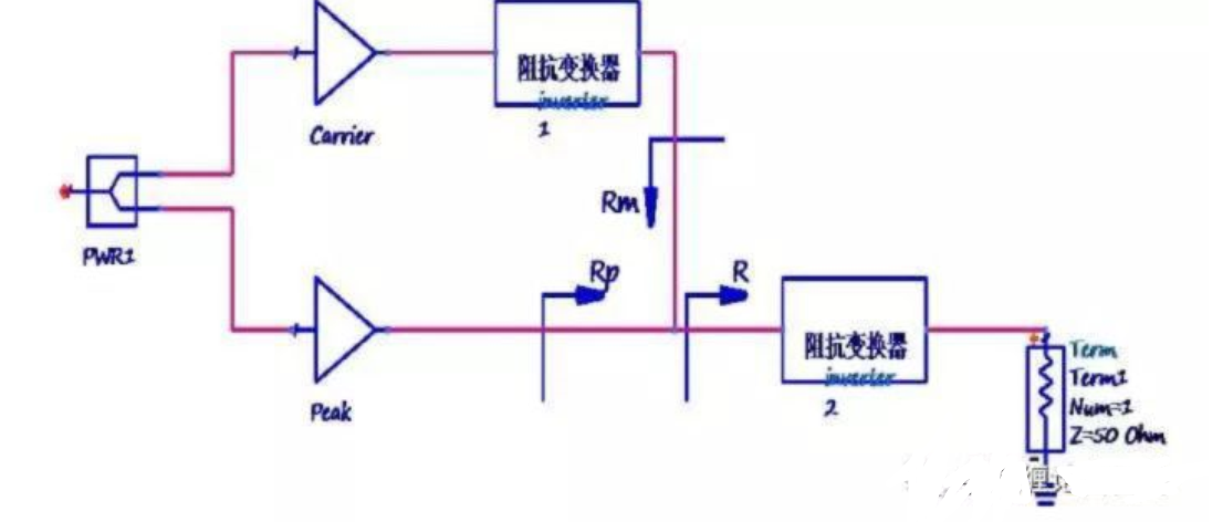
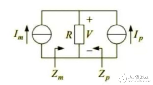
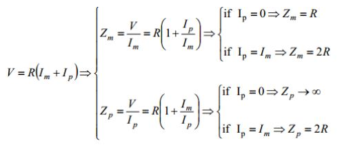
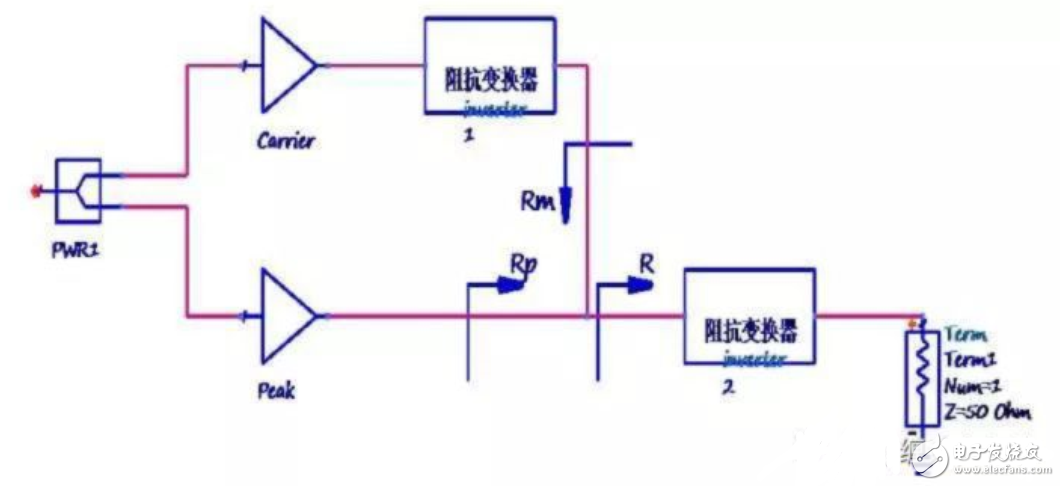
How does Doherty improve efficiency? Starting from the input, after a power splitter, the two-way Doherty boost efficiency refers to the efficiency when it can improve the back-off power. The source means that the circuit component that realizes the load traction is an active device, and in Doherty it refers to the power amplifier tube. Recently, I have been working overtime to locate problems, and people have been exhausted. This series of articles has been updated slowly. Today I am going to introduce the classic two-way Doherty power amplifier principle, and try to use the formula to explain the principle. Last time, the principle of load traction was roughly explained, explaining the mechanism of load traction lifting efficiency. This time, the book is based on the previous article. First, how to improve the efficiency of Doherty, and then talk about the active load traction, and then explain how active load traction can improve the efficiency of Doherty retreat. See Figure 2-1 directly. The picture is a typical two-way Doherty. Let me introduce it a little. Starting from the input (the map is in a hurry, the figure is not marked, that is the leftmost node), the signal is divided into two paths after passing through a power splitter. One way we call Carrier Road, also known as the main road; the second road is called Peak. Road, and call the auxiliary road. These two signals are finally concentrated in a place called the junction point (that is, the intersection of the two signal outputs in the figure) (just like the Yangtze River Yellow River comes out with a source (to be verified), and finally merges with the ocean in the ocean), then Hao The mighty flow into the load. Figure 2-1 Typical two-way Doherty architecture In fact, Doherty improves efficiency by referring to its efficiency in boosting back power. As mentioned in the first round, the current communication signals have a high peak-to-average ratio, and the power amplification works at the average power. For example, if the signal peak-to-average ratio is 6dB and the average power is 100W, then the output power of the amplifier should be up to 400W, so if you use a 400W class AB amplifier to retreat to 100W, then you are inefficient. Are afraid. Therefore, for the Doherty architecture, first, the total output power is non-isolated together by two (or more) power amplifier tubes. The carrier and Peak tubes in the above figure together provide output power. So the output power of each tube does not need to be so large; secondly, when outputting the average power (when retracting), usually only one power amplifier tube is working (only the carrier tube in the above figure, Peak is turned off), this tube is The efficiency of outputting this level of power is higher, which is nearly 30% higher than that of the ordinary AB type. The above picture is an example, which is the working process of Doherty. We fall back from the full power state to the mean power. In the full power state, the carrier path and the Peak path are saturated. When the output power gradually decreases, the peak path is gradually turned off, and the load impedance of the carrier path becomes larger than that in the saturated working state, so that when the power is backed down to the average power. Although the carrier current is reduced when the load is constant, the voltage swing is larger because the load impedance becomes larger, so that the same output power can be obtained, but the efficiency is greatly improved. The above explains why Doherty can improve efficiency at the back-off power---the load impedance becomes larger when the power is retracted. Let's talk about the active load pull on which the "load impedance becomes larger". We look at it separately: active + load traction. Load traction has already been said, then where is the source language? In fact, active means that the circuit components that implement load traction are active devices, and in Doherty it refers to power amplifier tubes. Here we make an agreement that the power amplifiers on the Carrier and Peak roads can be equivalent to current sources (it is ok so far). With this convention, let's analyze the working process of active traction. As shown in Figure 2-2, the main and auxiliary power amplifiers are equivalent to two current sources, named Im, Ip. The common load impedance of the two is R. Figure 2-2 Schematic diagram of active load traction Thus, the voltage across the load is the superposition of the voltage drop produced by the two partial currents. Let's do a scenario simulation now. First, assuming that the current Ip is 0, then only the current Im flows through the load R, and the voltage V on the load is Im*R. In other words, the impedance Zm seen from the current source Im in the direction of the load is now equal to V/Im, that is, equal to the load impedance R. Ok, let's assume that the current Ip slowly flows out of the current from the no-current state to the load. What is the impedance Zm from the current source Im to the load? Still divide the voltage by the current. At this moment, the voltage on the load is (Im+Ip)*R, and the current is Im (this is important because the current flowing into the load from the side of the current source Im is always Im, there is no change), then the Zm at this time It is (1+Ip/Im)*R. Smart, you will find that the current source Ip modulates (tracts) the apparent impedance of the current source Im. Assuming that the currents of the two current sources are the same, when the auxiliary circuit current is 0, the apparent impedance of the main circuit is the load impedance R, and the apparent impedance of the auxiliary circuit is the open state; when the auxiliary circuit is gradually opened, the current Ip is changed from small to large. The apparent impedance of the path changes from R to 2R. In this way, the modulation of the auxiliary path current injection completes the modulation of the apparent impedance of the main path. So many are trying to make this active load pulling process clear without writing a formula. In fact, the above pile is the following formula (still mathematical simplicity), please read if you are willing to see. Someone looked at the messy things above, and may have a question: How do these correspond to the Doherty amplifier's improved retreat efficiency? Next, let's talk about how to load the traction in Doherty (accurately for the Carrier Road), which will improve the efficiency of the retreat. For the sake of this, reattach Figure 2-1 here. In the most classic two-way symmetric Doherty, the power splitter is a 3dB power split, and the power amplifier tubes used in the main and auxiliary circuits are the same (the matching is also the same). When the input signal is relatively small (that is, when the output power is not large), the Peak circuit is turned off, does not work, and has no current. At this time, the impedance Rp seen from the junction point to the Peak Road is infinite and is in an open state. When the input signal power increases slowly, the peak path begins to open and a current flows into the load. As before analysis, the impedance Rm seen by the main road starts to gradually increase. When both paths are saturated, Rm becomes 2R. This process is the active load pull of the Peak Road to the Carrier Road. Then someone may have a question at this time: Isn't it true that Doherty is improving the efficiency of the fallback state (outputting less power)? According to your analysis, the output power is larger, the load impedance of the carrier path becomes larger (the efficiency becomes larger), and when the power is turned back (Peak path decreases the output), the load impedance becomes smaller (the efficiency becomes lower). Very good, in fact, careful students will find that in the carrier road, there is something called impedance transformer after the output of the power amplifier. This thing is actually a passive circuit, usually a theoretical analysis is replaced by a 1/4 wavelength conversion line. Students who have studied radio frequency should be clear that after the characteristic impedance of the 1/4 wavelength conversion line is determined, the impedance at both ends is inversely proportional, that is, the impedance of one end becomes smaller from small to the other, and the other end is changed from large to small. BMA Cable Mount Connectors,BMA Bulkhead Mount Connectors,BMA Flange Mount Connectors,BMA PCB Mount Connectors Xi'an KNT Scien-tech Co., Ltd , https://www.honorconnector.com