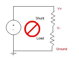
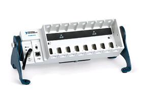
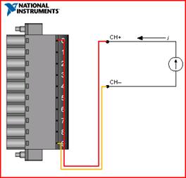
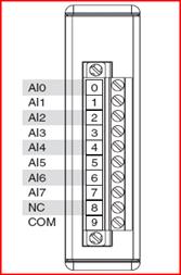
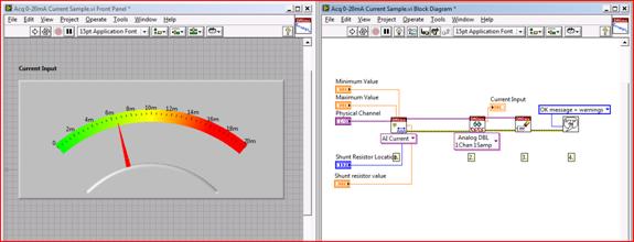
Based on PC data acquisition, measurement is performed through a combination of modular hardware, application software, and a computer. Although data acquisition systems have different definitions based on different application requirements, the purpose of each system to collect, analyze, and display information is the same. The data acquisition system integrates signals, sensors, actuators, signal conditioning, data acquisition equipment, and application software. Current introduction Although there are many ways to measure the current, the most common method is to perform an indirect measurement that measures the current through a resistor by measuring the voltage across a precision resistor according to Ohm's law. Current basis In solid conductive metals, there are a large number of electrons that are either mobile or free. When a metal wire is connected to both ends of a DC voltage source (such as a battery), the voltage source adds an electric field across the conductor. Once the connection is complete, free electrons in the conductor will be forced to the positive extreme under the effect of the electric field. Therefore, in a typical solid conductor, free electrons are the carrier of the current. For a current rate of 1 ampere, 1 coulomb of charge per second (ie, about 6.242 x 10¹⁸ electrons) flows through an imaginary conductor plane. In the early history of electricity, conventional currents were defined as the flow of positive charges. In a solid metal (such as a wire), the positive charge carriers do not move and only negatively charged electrons flow. Because electrons carry negative charges, the direction of electron flow is opposite to that of conventional currents. When solving a circuit problem, the actual current direction flowing through a particular circuit element is often unknown. Therefore, each circuit element is assigned a current variable and an arbitrarily selected reference direction. When the circuit problem is solved, the current value of the circuit element may be positive or negative. A negative value means that the actual current flowing through the circuit element is opposite to the selected reference direction. How to measure current measurement current There are two main methods of measuring current: one is based on electromagnetism, related to the early dynamic coil (Dasongvale) meter, and the other is based on the main theory of electricity Ohm's Law. Dasfarval current meter The Dassault galvanometer is an ammeter that is used to measure and measure current. It is an analog electromechanical sensor that generates a rotational deformation on a limited surface arc when current flows through its coil. The Dasongval current meter used today is made by winding a small rotating coil outside the permanent magnet. The coil is tied to a thin pointer that rotates around the calibration dial. A small torsion spring pulls the coil and pointer to zero. When a DC current passes through the coil, the coil generates a magnetic field. This magnetic field is opposite to that of the permanent magnet. The coil is twisted and pushes the spring, causing the pointer to move. The pointer is on the scale that shows the current value. Well-designed pole pieces make the magnetic field uniform so that the angle of the pointer deflection is proportional to the current. Other ampere meters Basically, most of today's ammeters are designed according to Ohm's law, the basic theory of electricity. Modern ammeters consist essentially of voltmeters and precision resistors. Using Ohm's law, accurate and cost-effective measurements can be made. Ohm's Law - Ohm's Law states that in a circuit, the current flowing between two points of a conductor is proportional to the potential difference between two points (or voltage drop or voltage) and is inversely proportional to the impedance between two points. The mathematical expression describing this relationship is: I = V/R Where I is the current in amps, V is the potential difference between two points in volts, and R is the circuit parameter, which is in ohms (equivalent to volts per ampere) and is called resistance. Current Meter Operation - Today's current meters measure the current of a specific signal through an internal resistor. However, when the internal resistor cannot measure a larger current, an external configuration is required. In order to measure a larger current, a precision resistor called a shunt resistor can be connected in parallel with the ammeter. Most of the current flows through the shunt resistor and only a small fraction of the current passes through the ammeter. This allows the ammeter to measure larger currents. As long as the desired maximum current multiplied by the value of the resistor does not exceed the input range of the ammeter or data acquisition device, any resistance is acceptable. When using this method to measure the current, you should use the smallest resistance value because it will cause the least interference to the existing circuit. However, the smaller the impedance, the lower the voltage drop, so you must make a compromise between resolution and circuit disturbance. Figure 1 shows a typical current measurement schematic using a shunt resistor. Figure 1. Connecting the shunt resistor to the measurement circuit With this method, the current is not directly input to the ampere meter or the data acquisition board but through an external shunt resistor. Therefore, as long as the voltage drop across the shunt resistor does not exceed the operating voltage range of the ammeter or data acquisition board, the theoretically measurable current value is infinite. Current convention Conventional current Conventional currents are common current measurement metrics in today's electronic circuits, transmission lines, and the like. They do not meet the transmission standards, and they can range from zero to large amperage. Current Loop/4-20mA Convention When the device needs to be remotely monitored or controlled by a pair of conductors, then an analog current loop is needed. At any moment, there is only one current level. The "4 to 20 mA current loop" or 4-20 mA is the analog electrical transmission standard for industrial instruments and communications. For the current loop signal, 4mA means no signal exists, 20mA means that the signal is 100% [1]. mA is an abbreviation for milliamps, which is one thousandth of an ampere. The 4 mA "live zero" allows the receiving instrument to distinguish between zero signals and damaged wires or bad instruments [1]. Although developed in the 1950s, today this standard is still widely used in industry. The benefits of the 4-20mA convention include manufacturers' widespread use, relatively low implementation costs, and the ability to combat electrical noise. In addition, with live zero, you can directly use the current loop to power low-power instruments, saving extra wire costs. Accuracy considerations The placement of the shunt resistor in the circuit is important. If the external circuit is common to a computer with an ammeter or data acquisition board, you should place the shunt resistor as close as possible to the ground of the circuit. If this is not the case, the common-mode voltage generated by the shunt resistor may be outside the ammeter or data acquisition board specifications, which can lead to inaccurate readings and may even damage the circuit board. Figure 2 shows the correct and incorrect placement of the shunt resistor. Figure 2 Shunt resistor placement Data Acquisition Equipment Measurement There are three different methods for measuring analog inputs. Please consult the document How to Make Voltage Measurements for more detailed information on each configuration. For example, consider the NI CompactDAQ USB data acquisition system. Figure 3 shows an NI CompactDAQ chassis and an NI 9203 analog current input module. Since the NI 9203 has a precision resistor inside it does not require an external shunt resistor. Figure 3. NI CompactDAQ Chassis and NI 9203 Analog Current Input Module Figure 4 shows the connection diagram for reference signal terminal (RSE) voltage measurements using the NI cDAQ-9172 chassis and the NI 9203 and the module pin definitions. In the figure, pin 0 corresponds to the "analog input 0" channel and pin 9 corresponds to the common ground. Figure 4. Current measurement in RSE configuration In addition to the NI 9203, a general-purpose analog input module (such as the NI 9205) can also use an external shunt resistor to provide current input. View Your Measurements: NI LabVIEW Once you have connected the sensor to the measurement instrument, you can use LabVIEW graphical programming software to visualize and analyze the data you need. Figure 5. Current Measurement in LabVIEW references: Bolton, William (2004). Instrumentation and Control Systems. Elsevier. ISBN 0750664320. Excerpt from: NI "General Measurement Guide"
Solar Street Light is mainly applied in engineering projects. With the advantages of high luminous flux, super long lifespan, average 70% energy save, low maintenance cost and wide color temperature options, it is a perfect replacement for conventional halogen and sodium street light.The Led lamp is made of high- quality aluminum alloy material, with unique air convection design. Easy to install and use,secure and reliable. It has infrared ray inductive probe, when someone is approaching, the light will be all light for 60 seconds. But the people is leaving away, the light will be reduce1/3 lightness automatically, to save the energy.
80W Integrated Solar Street Lights 80W Integrated Solar Street Lights,80W Smart Solar Street Light,80W Solar Street Lights,80W Integrated Solar Street Lamp Yangzhou Bright Solar Solutions Co., Ltd. , https://www.solarlights.pl
Current is the flow of charge. The standard unit of current is Ampere (A), which equals the flow of one Coulomb of charge per second.