I. Introduction This product integrates a micro-control computer chip, a digital signal processing chip, and a standard communication interface. It is compatible with RS-485 or RS-232 interfaces and can perform functions such as measurement, calibration, setting, remote measurement, and remote adjustment. Due to its small size, multiple functions, and high accuracy, it can be used for measurement, metering, and remote centralized meter reading and monitoring management in a variety of AC power applications. Excellent performance, low price, can effectively reduce user cost. specification: - 4-channel single-ended digital input high: 3.5V to 30V V. Structure composition (1), sound alarm, when there is an alarm, automatically send a music alarm; JIANGYANG Special Cables are shipboard wire, diesel engine dedicated cable, sensor dedicated cable, profibus cable, solid PE insulated radio frequency cable with solid PE dielectric, coaxial cable with physical-foamed polyethylene insulation used in CATV systems, RG Serials polyethylene insulation coaxial cable, muticore and symmetrical pair/quad cable for digital communications horizontal floor wiring-solid polyethylene insulate. Wire Cable,Special Cable,Tinned Copper Wire,Flame Retardant Shipboard Flexible Wire Jiangsu Jiangyang Special Cable Co,.Ltd. , https://www.jymarinecable.com
With the development of communication technologies and control technologies, centralized monitoring and management has become an inevitable trend in the development of building intelligent management. Due to the scattered distribution of office building power distribution rooms, distribution boxes, control switches, and air conditioners, it is difficult to timely and effectively understand the safe operation status of each distribution equipment; the elevator power is far away from the duty room, and it is difficult for the attendant to understand in real time. Elevator power status; building security monitoring points, fire monitoring points can only form a network to achieve centralized management. In order to realize the efficient and intelligent management of the power building, the electrical monitoring automation system for the power building was developed.
II. Overview of the building The power distribution system of the power management building of the Power Management Corporation mainly includes the lighting distribution of office buildings, power distribution, and the high voltage and low voltage distribution of the 6KV power distribution room. The office building lighting distribution system is mainly divided into two separate power distribution systems, the new building and the old building, and the low-voltage lighting power supply is provided by the 6KV power distribution room at the back of the building. A total of 12 floors of distribution power supply for the old building are provided by power distribution cabinets allocated on floors 1, 6, 9, and 11 respectively; the new building section includes a total of 11 floors of distribution power in the basement, and the power distribution base of the power distribution room in the new building. Row provided. The four power distribution cabinets of the old building provide power to the wall distribution boxes on each floor. The distribution box on each floor includes one incoming line and sixteen outgoing lines; the new building wall distribution box includes one incoming line and thirteen outgoing lines. . The 6KV power distribution room includes two parts: the high voltage chamber and the low pressure chamber. The high voltage chamber includes two incoming lines and a set of high voltage bus couples; the low pressure room includes two low voltage incoming lines, one low voltage bus coupler and 54 outgoing switches.
Third, the principle of work The electric building electrical monitoring automation system is a distributed control system of the distribution system. It adopts a three-level, independent module structure. The electrical measurement and control unit transmits the real-time data of the electrical status and important branches of the various circuits collected at the scene to the information processing unit. The information processing unit processes the received information, uploads the monitoring center unit and executes commands issued by the monitoring center unit. .
Monitoring unit: The central computer mainly plays a monitoring role and completes the human-machine dialogue. It analyzes various data transmitted from each monitoring unit, dynamically displays various areas, real-time operation information, and exceeds the alarm limit. The central computer has a database of operational information and stores monitoring and operational reports for more than half a year.
Information processing unit: PCC acts as an information processing unit and mainly completes data processing, information upload and release.
Electrical measurement and control unit: The main site data collection and control.
Fourth, intelligent module 1, R-8073N / W multi-function smart power harvesting module
- Number of measured paths: Three-phase current, voltage, 1 DI, 2 DO transformer positions Built-in (R-8073N)
External (R-8073W)
- Measured parameters: true rms voltage, power factor, active power, reactive power, frequency, power factor, input active power, output active power, total power, reactive power, apparent power, Total apparent power
- Input frequency: 47 to 75Hz
- Voltage range: 10~500V, higher voltage can be measured by applying voltage transformer and setting voltage ratio
- Current range: Basic range 0 ~ 5A, can measure large current through the applied current transformer and set current ratio
- Signal processing: 16-bit A/D conversion, 6 channels, each channel is synchronously sampled at 4KHz, real-time data of the module is 1 second of true RMS (refreshed every second)
- Overload capability: 1.4x range input can be correctly measured; instantaneous (10 cycles) current 5 times, voltage 3 times range is not damaged
- Output data: three-phase voltages Ua, Ub, Uc; three-phase currents Ia, Ib, Ic; active power P, reactive power Q, power factor PF, frequency f, active power Pa, Pb, Pc of each phase; Reactive power Qa, Qb, Qc; forward active power, reverse active power, forward reactive power, reverse reactive power, etc.
- Output interface: RS-485/RS-232, jumper selection
- Communication speed: 1200/2400/4800/9600BPS
- Communication protocol: ASCII command set and MODBUS/ASCII, MODBUS RTU protocol
- Accuracy rating: current, voltage 0.2, other 0.5
- Parameter setting: Module address, communication rate, voltage to current ratio can be set via communication interface
- Power supply: +10V to +30VDC or 220VAC
- With upper and lower limit alarm, phase loss alarm, overload alarm, overvoltage alarm, undervoltage alarm
- Built-in real time clock, provides year, month, day, hour, minute, second information, equipped with lithium battery, ensure the clock is uninterrupted for 10 years
2. R-8060/R-8060+ (4 isolated digital inputs/4 relay output modules)
Low level:0~1V
- Input isolation voltage: 5000V
- Input impedance: 3KΩ
- 4 relay outputs
- Contact capacity: 2A@220VAC, 2A@24VDC
- With Modbus communication protocol (R-8060+) 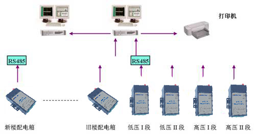
Sixth, system function:
1. Power Management High and low voltage grid systems intelligent centralized monitoring and control. By means of remote control, the management of the power supply system is optimized to allocate energy and save energy more effectively.
2. Fault location Various faults of the power supply and distribution system, lighting system, air-conditioning ventilation system, elevator system, and DC power supply system can be promptly and accurately reflected from the human-machine interface.
3, alarm management A) alarm information:
All alarms display detailed information about the alarm monitoring point, including the name and time of the occurrence.
B) Alarm level:
According to the severity is at least divided into three levels in order to more effectively and quickly deal with serious alarms. The user can decide the level of severity for different alarms.
C) Alarm output:
(2), image alarm, when there is an alarm, automatically pop up alarm information screen;
(3), SMS output, when there is an alarm, automatically sent to the designated mobile phone by SMS;
According to the alarm signal issued by the site, the monitoring center conducts fault diagnosis and failure analysis, and emits audible and visual alarms to provide fault diagnosis basis for operators; 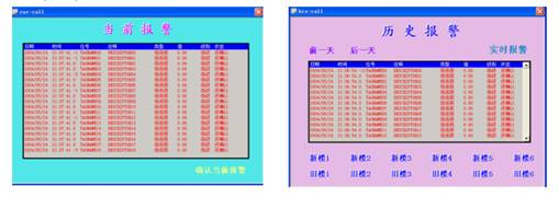
4, security management Set up multi-user, multi-level operation authority, only the operator enters the correct administrator name and password, in order to operate the control device to ensure the safe operation of the system. 
5. Web browsing Based on the main operating station, each operating station is connected via Ethernet to form a larger network system. And it is published on the Internet in a web-based manner. Administrators only need to install a standard browser on the client to realize monitoring and management of the entire building (group).
6. File management The system can automatically archive every control operation, manage the previous fault data and important data, and prepare it for analysis at any time. Each CPU has the following record accumulation: Accumulation of running, analog and pulse, and cumulative record of occurrences. If the cumulative number of records exceeds the user-defined limit, the system will automatically release the user-specified warning message.
7. Report output Various forms of reports can be output according to the needs of users.
Seventh, system characteristic:
1, intuitive:
Using a graphical management and monitoring interface, users can intuitively manage and monitor the operation of the equipment, including graphical system network structure, device monitoring interface, historical data and real-time data trend display.
2, reliability:
The design fully reflects the characteristics of decentralized control and centralized management. To ensure that each sub-station system can be independently controlled, and at the same time centralized management can be done on the central workstation, so that the entire system has a perfect structure and reliable performance.
Each level of equipment in the system can operate independently, that is, at the same time the different levels of the collection and distribution system (or different levels of structural organization form), the use of the interface is very convenient, while greatly increasing the reliability of the system.
3, advanced:
The superior remote communication function enables the control systems of different buildings to be linked to form a cluster system.
The openness and compatibility of the network structure ensure its ability to combine with advanced communication technologies, and ensure the continuity of the system structure at the time of product replacement.
4, economical:
The structure is modular, the control method is extremely flexible, and the maintenance and expansion of the control layer is extremely convenient. The building automation system can be easily expanded to save initial investment, and each part of the system can be put into use after commissioning. The system can meet your requirements for cost savings in property management. Putting in effective costs will ensure the comfort and safety of the office area.
5, scalability:
The modular configuration facilitates system expansion and integrates advanced, standard, reliable and easy maintenance.
VIII. Promotional Prospects This function is in line with the development direction of building automation, and increases the reliability of the safe operation of the distribution power supply of buildings and communities. The overall design meets the requirements of the current domestic building automation level, because this function can be integrated with other building monitoring to form a network system, which increases the reliability of the system operation, reduces the security risks, and saves costs, will be subject to the majority of users Welcome.