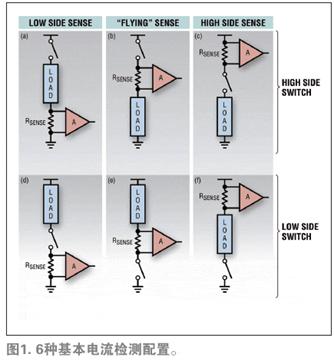
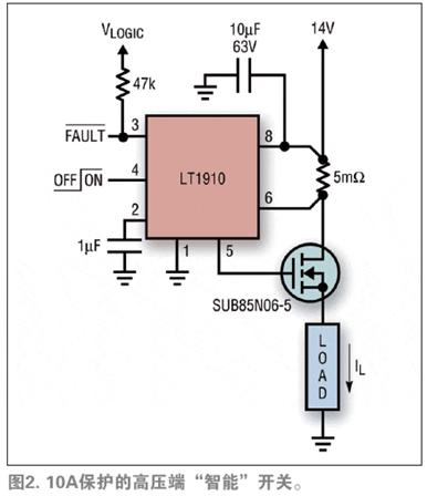
Modern automotive electrical system design is currently in the midst of one of the biggest changes in history. From revolutionary motor/generator hybrid electric propulsion and "fly-by-wire" electric drives to smart accessories for extended life and increased efficiency (eg strapless pumps and LED lighting), etc. Integrated into new vehicles. Users are increasingly looking to have automated on-board diagnostic systems and predictive maintenance capabilities, which has also led to the emergence of new vehicle body and engine management system designs. In many such systems redesign areas, an important piece of information feedback is the current used by a particular load. Current measurements are used to analyze whether the status is normal and provide a basis for fault protection and control rule implementation. The fundamental change in this area is that intelligent and efficient “closed loop†design is replacing the traditional “open loop†system of the past. This article refers to the address: http:// Basic current detection topology Although non-contact current measurement is achievable, this approach typically requires high cost instruments or expensive power supply unit products, so this approach is only used where cost and complexity allow. In the automotive field, low cost is a key factor, so the detection resistance measurement method is the most suitable. Connect a small value of the sense resistor (on the order of milliohms) to the load and measure the voltage drop across the resistor when powering the load to accurately derive the current value. There are basically six different topologies for the series connection of switches, loads, and sense resistors, as shown in Figure 1(a) through Figure 1(f). These topologies can be classified as high side switches or low side switches depending on the position of the switch relative to the load; and classified as low side detection, "floating" detection or high voltage end detection depending on the position of the resistor relative to the power rail. Each solution is probably the best solution for some specific applications. Another situation to consider is when a fault occurs, the fault varies depending on the load characteristics. As a rule of thumb, it is generally assumed that the most likely failure is to connect to the rack (electrically), either by a wrench touching a live exposed terminal, or by a wire worn by a sheath and a grounded metal part. Caused by contact. In this case, low-voltage end detection has inherent disadvantages. In most applications, the configuration of Figure 1(c) is a preferred topology because it allows the switching and monitoring functions to be brought together while maintaining fewer connections. Modern load and smart switch Since the introduction of power MOSFET devices, designers have seen them as potential replacements for relays. Modern N-MOSFET switches have on-resistance values ​​in the one-digit milliohm range, allowing the use of standard surface mount technology without awkward heat dissipation structures. A low-cost integrated circuit solution has been developed that provides a self-contained boost gate drive. These circuits also employ a fast fault protection mechanism so that the MOSFET is never at risk of failure. Linear Technology's LT1910 is such a "smart switch" control IC that uses a low-resistance high-side current sense resistor (similar to Figure 1(c)) to detect circuit overload and shut down before a damage occurs. MOSFET. As soon as the integrated circuit detects an overload condition, it sets a warning flag and periodically attempts to restart the load until the fault is cleared. Although this integrated circuit is essentially binary in nature, it is a good example of using current sensing to form a robust "closed loop" electronic relay solution as shown in Figure 2. Real-time current monitoring In addition to providing intelligent switching protection, current sensing allows for digitization after signal amplification and conversion on the sense resistor, and uses the digitized signal as an "analog" feedback signal for the control loop. Current monitoring can reveal the operating characteristics of many loads in real time. For example, the current consumed by the motor is proportional to its torque, so the trend of the bearing frictional resistance can be derived and the state of the various starters can be detected without the need for additional sensors. Other loads, such as lighting, are often driven in parallel using a common power source, so it is only a matter of accuracy to determine if certain parts of the load fail to open when the life has expired. A particularly simple integrated circuit solution to achieve this is the current sense amplifier, an example of which is the Linear Technology LTC6102, which is optimized for accurate one-way high-voltage automotive inspection. Figure 3 shows an example of a typical circuit that uses the LTC6102 to connect a general-purpose current sense output to an analog-to-digital converter (ADC) input. Note that the output of the LTC6102 is current, so the reconstructed load (R2) can be placed at a distance from the integrated circuit without introducing ground loop errors. Since the integrated circuit is extremely accurate, even RSENSE values ​​below milliohms are practical, so heat and voltage losses are minimal. The added components D1 and R3 in this circuit provide power reverse transient protection. Table 1 lists some of the available sense amplifiers and their basic characteristics. Factors to consider when using pulse-modulated loads For high-frequency pulse width modulation (PWM) techniques to produce variable performance levels of duty cycle modulated loads, there are other factors to consider when designing current monitoring circuits. The main point is that the response time needs to be fast enough to respond to the fault condition in the connected portion of the waveform. Another point is that the switching action should not cause too much interference with the current reading fidelity. In general, the configuration of Figure 1(c) again provides the best results because the impedance of this circuit is low and the common mode problem is minimal. Where an average load current (DC component) is desired, post-filtering used in the analog or digital signal processing (DSP) domain can be used to remove the frequency components associated with the PWM. The average supply current value is related to the load current. This value provides a good indication of the subjective effect, whether it is the intensity or the power of the lamp. Monitor the current of the H-bridge driver An H-bridge driver can be thought of as a pair of half-bridges that operate with complementary signals to produce a bidirectional differential output. Each half bridge can be seen as an extension of the unidirectional circuit of Figure 1(c), which adds a low side switch in parallel with the load in the configuration of Figure 1 (c). Figure 4 shows a circuit consisting of an LTC6103 that produces a differential output suitable for directly driving the ADC. Circuits like this are suitable for motors in mechanisms such as window lift, ambient atmosphere control, etc., and can perform reverse motion wherever they are. Note that for load-ground faults, the low-side MOSFET is not subject to excessive stress, so monitoring each half-bridge on the high-voltage side provides all the information needed. The load current can be determined by the difference in unidirectional current readings of the two half bridges. In addition, due to the signed value control, when a high-voltage switch is 100% turned on, accurate measurement of the load current does not require duty cycle correction. Conclusion In modern car development, electronic drive functions are skyrocketing. Although the economical control design requires ruggedness, it adds a diagnostic function that monitors the load current in the system in a closed loop. Whether the driver is single-ended or H-bridge, high-voltage current sensing is the most practical way to implement monitor functionality. The LT6100 series offers a wide selection of current sense amplifiers that meet the specific needs of a wide range of applications, such as component accuracy/efficiency, operating voltage, high temperature operational monitoring solutions, and cost-effective high-side monitoring solutions.
Plastic technology is the use of thermoplastic polymer materials has the property of state variable, namely with sticky flow under certain conditions, and the characteristics of temperature and recoverable solid, and use the appropriate method and special tools inkjet, according to the requirements on the sticky flow condition into form, for the design and then curing at room temperature. This drip molding process is applied to lamp strings and can be used for many shapes. This type of lamp can be placed outdoors and has an IP44 waterproof rating, which can be made 3D design. The color of light can be white, warm white , colorful, pink, etc. The design can be customized.
3D Acrylic Lights 3D Acrylic Lights,3D LED Night Light,3D LED Acrylic Light,LED Acrylic Decoration Light Heshan Jianhao Lighting Industrial Co., Ltd. , https://www.sunclubtw.com