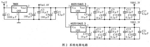
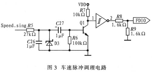
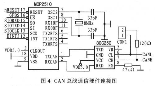
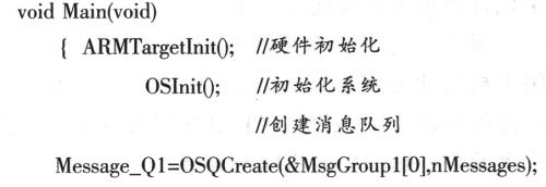
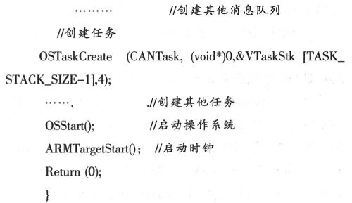
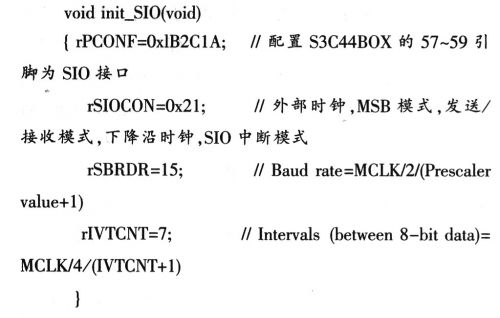
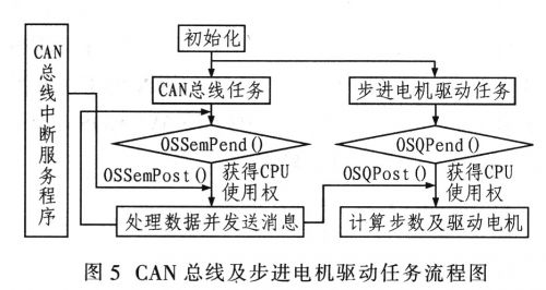
1 Introduction This article refers to the address: http:// Automobile instrumentation is an information exchange interface between the driver and the car, and plays an important role in car safety and economic driving. In recent years, with the development of automotive electronic technology, the display information of automobile meters has also been increasing, and the traditional mechanical pointer type automobile combination meters cannot meet the needs of current use. In particular, computers, microelectronics and various fieldbus communication technologies are widely used. Intelligent digital instruments with embedded microprocessors as the core will be an inevitable trend in the development of automotive instruments. This paper presents an embedded automotive digital instrument design. 2 hardware design The main signals that the car instrument needs to deal with are: vehicle speed, engine speed, water temperature, oil quantity, and various switching or alarm signals. Among them, the engine speed signal and the front and rear lamp signals are obtained from the CAN bus (engine electronic control module and front and rear lamp electronic control module), and the vehicle speed signal, water temperature, oil quantity and other switching quantity signals are obtained from the corresponding sensors. The structure of the automobile digital instrument system is shown in Figure 1. The system uses the step meter display for the vehicle speed, engine speed, water temperature and oil quantity information. The mileage information is displayed by LCD, the switch quantity or alarm signal is LED display, and the serial port EEPROM is used. Store mileage information. The MCP2510 with the SPI interface of Microchip and the transceiver 80C250 form a CAN node for communication with other CAN nodes of the vehicle. 2.1 MCU, external expansion memory and mileage storage circuit The system uses Samsung's ARM7TDMI device S3C44BOX as the main controller. The S3C44BOX is a 16/32-bit RISC processor that operates at up to 75 MHz and is rich in internal resources. Since there is no internal memory in the S3C44BOX (internal SRAM is used for buffering), it is necessary to use the bus to expand external memory, including program memory and data memory, using 16 Mbit: FlashSST39VF160 and 64 Mbit SDRAM HY57V641620 as program memory and data memory, respectively. The system also uses a piece of AT24C04 storage device to store mileage information. The AT24C04 is a 4 Kbit serial memory that uses I2C bus to store mileage information. 2.2 power supply and reset circuit The automotive digital instrumentation system is powered by a car battery. The voltage of the car battery is about 12 V. The system requires 5 V, 2.5 V and 3.3 V operating voltage. The S3C44BOX core operating voltage is 2.5 V. The operating voltage of the I/O port. It is 3.3 V, and the conditioning circuit and some driver devices require a working voltage of 5 V. Therefore, the system uses the 7805 regulator as the 5 V voltage converter, and uses AS2515AU2.5 and AS2515AU3.3 as the 2.5 V and 3.3 V voltage converters respectively. Mileage information can be stored in time when power is off, and a 1000 μF capacitor is required for the power ground. When power is off, the large capacitor can ensure that the S3C44BOX works for a period of time and completes the storage of mileage information. The reset circuit uses a dedicated reset circuit IPM811 to achieve stable startup of the system. Figure 2 shows the system power circuit. 2.3 Processing circuit of vehicle speed, water temperature, oil quantity and switching quantity Since most of the cars work in harsh environments, they will interfere with the vehicle speed sensor signal. Therefore, the vehicle speed pulse signal needs to be processed before input to the interrupt port EINT0. Here, the RC filter, the triode amplification and the Schmitt shaping method are used to adjust the vehicle speed pulse signal. The vehicle speed pulse conditioning circuit is shown in Figure 3. The water temperature and oil quantity signals are resistance signals, which must be converted into voltage signals, and then their voltage signals are input to the AD port of the S3C44BOX. The other switches are filtered and stepped down to the I/O port of the S3C44BOX. 2.4 CAN bus communication circuit S3C44BOX has no SPI interface, but has SIO interface. The SIO module can transmit and receive data bits on the rising edge or latch the data bit on the falling edge. Therefore, it can be increased by setting the register corresponding to the SIO module of S3C44BOX. Along the transmit data, the falling edge receives the data, which matches the SPI bus timing of the MCP2510. The CAN bus communication circuit is shown in Figure 4. Stepper motor head circuit, etc. Among them, the stepper motor uses XXP.168, the stepping motor for automobile instrument, and the I/O level of the dedicated four-channel stepping motor driver X12.017.S3C44BOX is 3.3LVCMOS level, and X12.017 is 5VCMOS. Flat, need to use 74LVX4245 level conversion. 3 software design 3.1 operating system μC/OS-II is a free, open source embedded real-time operating system developed by Jean J-Labrosse. μC/OS-II is a priority-based deprivationable kernel. All tasks in the system have a unique priority level, which is suitable for occasions with strong real-time requirements. μC/OS-II provides a variety of system services such as message mailboxes, message queues, semaphore management, and time delays. The real-time kernel makes CPU utilization more efficient. 3.2μC/OS-II transplantation and configuration on ARM The source code of μC/OS-II is not only written in assembly language, but most of the code is written in C language, so μC/OS-II is highly portable. Porting μC/OS-II on ARM mainly writes three source files, namely OS_CPU.H, OS_CPU.C, OS_CPU_A.S. Complete the required basic configuration and definition in OS_CPU.H (Define data type, definition enable) And disable interrupt macros, etc.; OS_CPU.C mainly transplants OS-TaskStkInit(), OSTaskCreateHook(), OSTaskDelHook(), OSTaskSwHook(), OSTaskStatHook(), OSTimeTickHo-ok(), etc.; OS_CPU_A.S mainly completes OSStartHighRdy (), transplantation of four assembly functions such as OSCtxSw(), OSIntCtxSw(), and OSTickISR(). 3.3 System Tasks and Analysis "Task division" for a specific embedded application system is the key to real-time operating system application software. Whether the task division is reasonable will directly affect the software design quality. The system mainly has eight tasks, namely, vehicle speed pulse measurement task, CAN bus task, water temperature sampling task, oil sampling task, switch processing task, mileage record and LCD display task, stepping motor drive task, WDT task. Tasks communicate and share data through message queues and semaphores. The system master program is as follows: The main program creates each task after completing the initialization (hardware initialization ARMtarge-tInit(), μC/OS-II initialization OSInit(), creating message queue, etc.), then calls OSStart() to start the operating system, and starts the clock ARMTargetStart(). . In μC/OS-II, each task is concurrent, but with different priorities, has its own task stack, and communicates and shares data between messages through message queues and semaphores. The task adopts an infinite loop structure, and each task abandons the CPU usage right by delaying or waiting for the semaphore and the message queue, so that when the clock pulse arrives, an interrupt switching task is generated, and the system turns to a ready high-priority task. The task runs again when the time or semaphore and message queue arrive. The system uses the TimerO timer interrupt as the system clock pulse controller and establishes the semaphore in the required tasks. The system tasks are as follows: 1) Vehicle speed pulse measurement task: The pulse signal is connected to EINTO, and the timer 1 is used to measure the number of pulses in t time, and the data is sent to the message queue. 2) CAN bus task: The CAN bus task waits for the interrupt service program to send, receives the semaphore of the CAN bus data, and after obtaining the CPU usage right, the CAN bus task processes the CAN bus data and sends it to the message queue, and waits for the received semaphore again. . 3) Water temperature and oil sampling task: Timing sampling analog quantity and sending the sampled analog value to the message queue. 4) Switching processing task: According to the state of the switching quantity, the LED is turned on or off, and the delay is delayed. 5) Mileage record and LCD display task: When the vehicle speed pulse value is added to the 0.1 km count value, the semaphore is sent to the task, the task gets the semaphore and then enters the ready state, and the CPU usage right is obtained during the task scheduling, which is displayed and recorded. Mileage information, continue to wait for the received semaphore after running. 6) Stepping motor drive task: first wait for the message queue, then identify the information content according to the task of sending the message, and drive the stepping motor to rotate the corresponding step according to the data in the queue, and wait for the message in the queue again after running. This task gives the second highest priority. 7) WDT task: used for monitoring, improving system reliability, task priority, delay. 3.4 CAN bus task and stepper motor drive task flow Since the SIO interface pins of the S3C44BOX are multiplexed with the standard I/O ports, the S3C44BOX pins 57 to 59 must be set as the SIO interface, and then the SIO module corresponding registers can be configured to make the SIO timing and the MCP2510. The SPI interface protocol is consistent and can be implemented by initializing the SIO function. As shown in Figure 5, after the initialization is completed, the main program initiates the CAN bus task and the stepper motor drive task. The two tasks enter the wait semaphore and wait for the message queue. After the CAN bus is interrupted, the interrupt service program releases the semaphore, making The CAN bus task enters the ready state, after it obtains the CPU control, processes the data, and then sends the data to the message queue, so that the stepper motor drive task enters the ready state, the motor task obtains the CPU usage right through the task call, and then according to the message. The data in the queue calculates the number of drive steps required to drive the motor to rotate. 4 Conclusion Using S3C44BOX and embedded real-time operating system μC/OS_II, a high-precision, high-sensitivity, stable and stable embedded bus digital instrument is designed. S3C44BOX is rich in resources and fast in execution. It can expand many functions, such as IC card, GPS, black box, etc. In addition, the embedded real-time operating system simplifies the application and can call system tasks efficiently and in real time. Therefore, the digital instrument system of this car can be very A good solution to the problem of automotive instrumentation towards comprehensive informationization.
In 2017, Touchwo
1080P full HD more fluently and perfectly.
Base with screw design in the floor mat to suit for all kind of grounds ( install wheels is optional)
Led Interactive Advertising Player Touch Screen Wall Display,Lcd Advertising Player,Lcd Digital Signage Display,Led Interactive Advertising Player Guangzhou TouchWo Electronics Co.,Ltd. , https://www.touchaio.com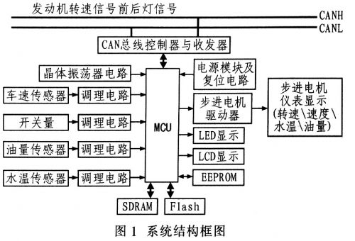
Grade lcd/LED display panel from all over the world famous brand.with top-rated decoding technology,playing