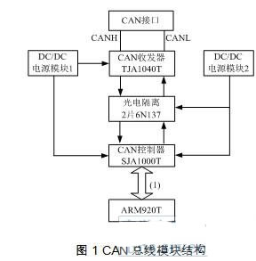
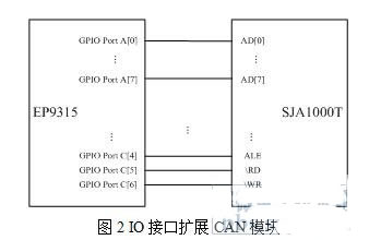
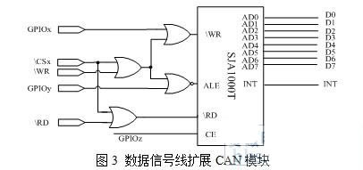
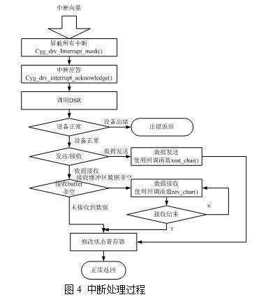
1 Introduction This article refers to the address: http:// With the gradual automation and modernization of industrial control systems, fieldbus control systems have received more and more attention and application. CAN bus is a kind of field bus with simple development and high cost performance. Compared with other fieldbuses, CAN communication controllers have the largest number of manufacturers, the most complete varieties, and the most widely used applications. Based on the intelligent and complex improvement of the fieldbus control system, as the core component of the fieldbus microprocessor, the traditional 51 chip, even ARM7 has gradually failed to meet the needs, ARM9 has become a suitable choice. However, many ARM9s do not have an integrated CAN interface, and expanding the CAN interface has become a top priority. And ARM9 separates the data address bus, and the CAN controller multiplexes the data address bus, so that the CAN extension cannot blindly copy the 51 processor. In the CAN module driver development, the existing data is often only introduced for the driver development on the Linux system, and the real-time requirements of the fieldbus control system make the Linux system give way to more real-time operating systems. This paper introduces a control system based on ARM920T fieldbus, details the two ways of extending CAN bus, and gives the steps of driver development of CAN module in real-time operating system eCos, and finally two extensions. A brief comparison was made. 2. Introduction to fieldbus control system The fieldbus control system uses EP9315 as the core processor. EP9315 is an industrial grade processor based on ARM920T developed by Cirrus Logic. In addition to the external CAN bus interface, the fieldbus control system also expands 64Mb SDRAM and 32MB FLASH, with PCMCIA interface, E PROM interface, 512kb SRAM, IDE interface, real-time clock, video display, color VGA TFT LCD touch screen, Support analog VGA connection, video decoding support compressed video output and S-VIDEO output, PS/2 keyboard, three USB interfaces, three serial interfaces, audio interface, 1/10/100Mbps Ethernet interface, infrared receiving port; The digital and intelligent control system can realize multiple functions, localize the control function of the system, improve the reliability and real-time of the system, and simplify the structure of the system. The system structure of the multi-interface makes the expansion, modification, and disassembly of the system more flexible and convenient. 3, hardware system expansion 3.1 CAN bus module structure This article uses SJA1000T as a CAN controller to extend the CAN module. The SJA1000T is a stand-alone CAN bus controller for automotive and general industrial environments, with all the necessary features to complete the CAN high-performance communication protocol; the SJA1000T with simple bus connection performs all functions of the physical layer and the data link layer. Support CAN2.0 protocol. The CAN bus transceiver TJA1040T is an interface chip between the CAN controller and the physical bus, which enhances the driving capability of the bus, thereby increasing the communication distance of the CAN bus and enabling more nodes to be hung on one bus. In order to enhance the anti-interference ability of the CAN bus node, the TXO and RXO of the SJA1000T are not directly connected to the TXD and RXD of the TJA1040, but are connected to the TJA1040T through two optocoupler isolation chips 6N137. The electrical isolation between the transceiver and the controller is well realized, and the intelligent node core circuit is protected safely; and the electrical isolation between the CAN nodes on the bus is realized. It should be emphasized that in order to achieve such electrical isolation, the DC power supply on both sides of the optocoupler device must be two DC power sources that are not directly electrically connected and isolated. Therefore, it is realized by two DC-DC isolated power supplies. In order to further enhance the security and anti-interference ability, a current limiting resistor can be connected in series between the bus transceiver TJA1040T and the CAN bus to avoid the TJA1040T being subjected to overcurrent impact. At the same time, in CANH and CANL, the filter capacitor is connected in parallel with the ground, which can filter the high-frequency interference on the bus and have certain anti-electromagnetic radiation capability. In addition, when the communication signal is transmitted on the line, the signal will be reflected when it is transmitted to the end of the wire, and the reflected signal will interfere with the transmission of the normal signal. In order to eliminate this effect, a matching resistor can be connected at both ends of the CAN bus to match the bus impedance and eliminate the reflection. If these measures are ignored, the anti-interference and reliability of data communication will be greatly reduced, and even communication will not be possible. 3.2 CAN module and ARM9 two connection methods SJA1000T data address bus multiplexing, and the entire ARM9 series including ARM920T data and address bus separate. This makes its connection with the ARM9 series not like the traditional expansion connection for the 51 MCU series. This article gives two extension methods: all IO port connection mode and minimum IO port data signal line connection. 3.2.1 IO interface connection The general purpose IO port of the microprocessor provides an easy way to control the SJA100T. The EP9315's GPIO signal provides a great deal of flexibility to meet the SJA1000T time requirements. The SJA1000T data address multiplexing bus is all connected to the universal IO interface of the EP9315. The other signal lines WR, RD, ALE ... are also connected to the IO interface. Refer to Figure 2 for the specific connection method. 3.2.2 Data signal line connection In addition to all the CAN modules controlled by the IO port, the ARM9 data lines and signal lines can be used to implement the expansion of the CAN module. The connection circuit is shown in Figure 3. Where the signals other than SJA1000T are the signal pins on the EP9315 chip, the SJA1000T data address multiplexing bus is connected to the EP9315 data line. GPIOx, GPIOy, GPIOz can be any EP9315 GPIO pin, but choose The GPIO port of the same channel will make programming easier. Note that the INT of the SJA100T can be connected to the INT of the CPU or to the general-purpose IO with interrupts. In EP9315, channels A, B, and F of GPIO have an interrupt function. 2 and 3 are schematic diagrams. Specifically, since the EP9315 signal has a high level of 3.3V and the SJA1000T has a high level of 5V, it needs to be level-matched by a level matching chip such as 74LVC245. 4, drive development Since the fieldbus control system has real-time requirements in many occasions, the fieldbus control system uses real-time eCos as the operating system, and the CAN driver is also extended on the eCos operating system. The design of the device driver for the eCos system mainly revolves around DEVTAB_ENTRY and DEVIO_TAB. The work of adding a new device is to implement the fields of the two entries and write the underlying functions related to the hardware. Through the analysis of the driver structure level, the development of CAN bus driver is divided into four steps: The first step: register a new device with the kernel; The second step: develop the driver basic IO function; The third step: implement the interrupt processing function; Step 4: Bind the device to an interrupt and verify it. The specific implementation process is as follows: 4.1 Registering a new device with the kernel When registering a new device with the kernel, the hardware-independent part of the original driver can still be used. For example, the device I/O function table, the hardware-related part needs to be designed by itself, including the device descriptor, device name, and device initialization program. Init, lookup program lookup and extend the data structure of the CAN bus. Expanding the CAN bus data structure Can_bus is a set of data structures used to describe all operations performed on the device. The data structure of the can bus is generated by the macro Can_bus, and the prototype of the macro Can_bus is: Can_bus(1,funs,modereg,intrenreg,bustime,outpctr,clkdiv,acptcode,acptmask,flag) The parameters are as follows: L-the language identifier of the data structure Funs interface function group, that is, hardware interface function. The flags driver initially represents the value. Modereg working mode initial value Intrenreg interrupt allows initial value Bustime bus clock 1, and bus clock 2 initial value Outpctr output control Clkdiv time sharing Acptcode acceptance code Acptmask acceptance mask When generating the device table entry of the CAN bus, the data object Can_bus of the can bus is first created and all the above parameters are initialized. The Can_bus data object identifier of the extended CAN bus is EP9315_can_bus. The device table entry object for expanding the CAN bus is implemented as follows: DEVTAB_ENTRY (EP9315_can_io0, CYGDAT_IO_CAN_EP9315_CAN0_NAME, 0, &cyg_io_can_devio, EP9315_can_init, //Expand the initialization function of CAN EP9315_can_lookup, //Expand the CAN lookup function &EP9315_can_bus //CAN data structure Can_bus ); 4.2 Developing Driver Basic IO Functions This part of the function refers to the hardware-related part of the driver interface function, which is the funs interface function table in the Can_bus data structure. The funs function table is defined by the following macro: CAN_FUNS(l,putc,getc,set_config,start_xmit,stop_xmit) The parameters are as follows: l is the C language standard of the funs function table. Putc function: bool (*putc)(can_bus *priv, unsigned char c) This function sends a character to the serial port. Returns true if the transmission was successful, otherwise returns false. Getc function: unsigned char (*getc)(can_bus *priv) This function reads a character from the device interface. It is only used in non-interrupt mode, waiting for a character by querying whether the device is in the ready state. Set_config function: bool (*set_config) (can_bus *priv, cyg_can_info_t *config) This function is used to configure the specified port. Returns true if the hardware configuration is successful, false if the port does not support the given configuration parameters. Start_xmit function: void (*start_xmit)can_bus *priv) In interrupt mode, this function enables the sender to allow the generation of interrupts. Stop_xmit function: void (*stop_xmit)(can_bus *priv) In the interrupt mode, when the data is sent, the function is sent to the hexadecimal sender, and the sigma transmission interrupt is generated. Start_recv function: void (*stop_xmit)(can_bus *priv) Stop_recv function: void (*stop_xmit)(can_bus *priv) 4.3 Send Interrupt Handling Function The CAN bus is responsible for processing the interrupt in the interrupt mode. The interrupt function routine is the interrupt service routine ISR and the interrupt lag service routine DSR. There are three main modes for interrupt processing. The first mode is to complete all device processing in the interrupt service routine ISR, the second is implemented in the interrupt lag service program DSR, and the third is to postpone the processing of the device to Interrupted within the thread. The second mode is used in the design of the driver. In this mode, the interrupt handler ISR simply prevents the generation of new interrupts by programming the device or by directly calling the cyg_drv_interrupt_mask() function, and then calls the DSR for further processing. The DSR does most of the hardware processing and may generate a signal to a condition variable to wake up the new interrupt. Finally, the DSR calls cyg_drv_interrupt_unmask() to re-enable the interrupt. The interrupt processing process is as shown: 4.4 Binding Device Interruption The initialization function of the device driver is called during the system initialization process or when the device is initially used. The initialization function not only sets the parameters of the device, but also assigns the corresponding data structure to the device: for example, input and output buffers, etc., and finally interrupts the device. Bind. Each device generates a corresponding interrupt object during initialization, and all interrupt objects are stored in the system's interrupt vector list. When an interrupt occurs, the system searches for the corresponding interrupt object according to the interrupt code to the interrupt vector list, and then jumps to the position of the interrupt handler of the interrupt object record. The macro cyg_drv_interrupt_create(vector, priority, data, isr, dsr, handle, intr) is used to generate the interrupt object of the device. Among them, vector is the interrupt vector, priority interrupt priority, data is the data pointer, isr is the address of the interrupt handler ISR, dsr is the address of the interrupt lag handler DSR, handle is the return handle, and intr is the location where the interrupt object is stored. The macro cyg_drv_interrupt_attach(interrupt) is used to add an interrupt vector to the interrupt vector list. The parameter interrupt is the handle of the interrupt to be connected. After the device is interrupted, the system will find the corresponding interrupt vector when the device generates an interrupt, and then hand over the control to the interrupt handler for interrupt processing. 5. Comparison of two expansion methods For two different CAN and ARM9 connection modes, the IO port connection is intuitive and simple; and the data signal line connection can save IO port and give the CPU more development space. The difference between the two is not big, mainly reflected in the implementation of the underlying data read and write timing. The former is simple and easy to write and understand. The latter is only slightly more difficult to understand the timing, and does not make the code more verbose. 6, the conclusion This paper expands the CAN bus module on the fieldbus control system, explains in detail how to extend the CAN bus module on ARM9, gives the full IO port expansion and the use of data signal line expansion two ways; and explains in detail how to be highly real-time The CAN driver was developed on the operating system eCos; finally, a simple comparison was made between the two extensions. The fieldbus control system has been well applied in the National 11th Five-Year National Defense Project. At the same time, it also provides a good reference for the construction and transformation of large and medium-sized state-owned enterprise automated production lines and the realization of power system automation. references [1] Shi Jiugen et al. CAN fieldbus system design technology [M]. Beijing: National Defense Industry Press, 2004. [2] Yan Kuanming. CAN bus principle and application system design [M]. Beijing: Beijing University of Aeronautics and Astronautics Press, 1995. [3] Wang Jingqi et al. Embedding is a configurable real-time operating system eCos technology and implementation mechanism [M]. Beijing: Publishing House of Electronics Industry, 2005. [4] Zhang Shaozhong, Wang Hui. Implementation of CAN bus intelligent node based on SJA1000[J].Application of Electronic Technique,2006(8):22-25. [5] Wang Songyue, Yang Fuxing. Device Driver Development Based on ARM920T Embedded Communication Control System[J]. Electric Power Automation Equipment, 2006.26(6):75-78.WANG Song-yue, YANG Fu-xing, Driver development for embedded Communication control system based on ARM920T[J]. Electric power Automation Equipment,2006,26(6):75-78. [6] Freund L, Dupont D, Israel M, Rousseau F. Overview of the ECOS project [J]. Rapid System Prototyping, 1997 'Shortening the Path from Specification to Prototype'. Proceedings, 8th IEEE International Workshop on 24-26, 1997.6:39-43. [7] Anthony J. Massa. Embedded Software Development with eCos [J]. PRENTICE HALL, Publishing as Prentice Hall Professional Technical Reference, 2003, 7-10, 315-322. [8] How to Connect NAND Flash Memory to an EP93xx [J]. http:// 2005.2.
Wire harness and the surrounding parts shall be even and sufficient distance shall be kept from the heat source,
Considering the protection against electromagnetic interferencee,
Consider assembly technology, maintenance technology,
Grounding wire layout,
Heat dissipation of wire harness and fuse box
Car Seat Harness,Power Seat Wiring Harness,Power Seat Harness,Right Seat Wire Harness Dongguan YAC Electric Co,. LTD. , https://www.yacenter-cn.com