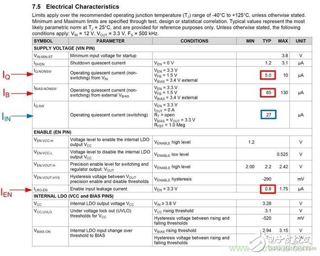
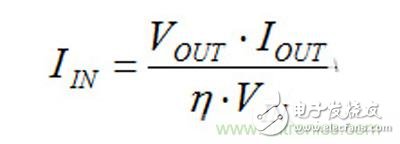
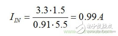
When this input is connected to the output of the regulator, this bias current acts as an additional load on the converter output. As with all other loads, this load is converted down by the ratio between the input voltage and the output voltage. It is the preferred connection because it reduces input current and increases efficiency. Now let's go back to the no-load input current. You sometimes can't find this input current in the datasheet, or it's not specified under your desired conditions. In this case, you can use Equation 1 to estimate the no-load input current of a buck regulator. Since this equation does not account for the losses in the converter, it gives an estimate of the best case. The first data called IQ is the non-switching quiescent current I talked about in the previous section. For the next data item, IEN is the current that enters the regulator enable input. Many converters require a certain amount of bias current to flow into the enable input. If the enable pin is connected to the input supply to turn on the regulator, then you must take this current into account; otherwise, this value is zero. The data item IDIV is the current in the feedback divider, which can be easily calculated using Equation 2: The data item IB represents the current flowing into the bias input I just talked about. Let's take the example of a 3.5V to 36V, 3A synchronous buck converter SIMPLE SWITCHER? LM43603. The following typical values ​​are available in this data sheet (Table 1). Table 1: LM43603 Data Sheet If you are converting a 12V input to a 3.3V output and the total resistance of the feedback divider is 1M?, Equations 1 and 2 give the following no-load input current values: One thing to note is that for the LM43603, as shown in Table 1, this data sheet represents the no-load input current under typical conditions. The 30μA current value I calculated is a bit different, but for rough estimates, this value is very close. These equations tell you that the no-load input current depends on the input voltage, output voltage, and other "static" currents. You will find that the input current will increase as the output voltage increases and the input voltage decreases. Therefore, the best practice is to use an equation to estimate the no-load input current and then measure the actual value under real-world conditions. You can also use the efficiency curve to calculate the input current of the DC/DC converter, but this current value is not the current value without load. In theory, the efficiency at zero load is zero, so you must estimate the no-load supply current using the method I described in this article. Under any other load conditions, you can use the efficiency curve in the datasheet, along with Equation 3, to complete the calculation: Here, η is the efficiency value under the required conditions. Taking the data sheet of the SIMPLE SWITCHERLM22670 3A buck regulator as an example, the load is 1.5A, and the efficiency at the input voltage and output voltage of 5.5V and 3.3V is about 91%. This gives your input current approximately: It is not difficult to use and estimate the input current found in the data sheet, provided that the values ​​you see are appropriate for the particular application. This range of extremely rugged 'skeleton' cable drums is particularly suited to life on the road but also at home in a TV or film studio. They are constructed from heavy-duty, welded, steel tubing, on to which an overall passivated zinc plate is applied. A traditional two-flange type is suitable for triax camera cable, multicore audio cable and heavy-duty power cables. An innovative three-flange design is suitable for coiling and protecting the inner 'tail' of SMPTE 311M hybrid fibre camera cable. An optional combined trolley and reeling stand is available for transporting the drums. Skeleton Reel,Steel Tube Reel,Galvanized Reel,Studio Reel,Cable Trolley NINGBO BEILUN TIAOYUE MACHINE CO., LTD. , https://www.spool-manufacturer.com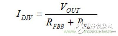
DC/DC converter data table helps complete static current decryption
Many DC/DC converters have an internal low-dropout linear regulator (LDO) that powers the converter's internal circuitry. In current regulators, the input to the LDO is typically available as an external pin to the converter. It is often referred to as the “bias pinâ€, however, please check the data sheet first to make sure it is on the converter.