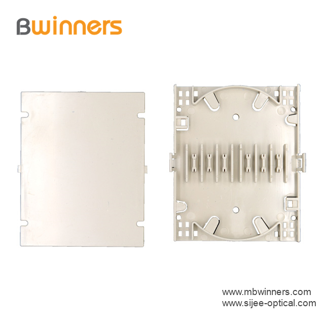
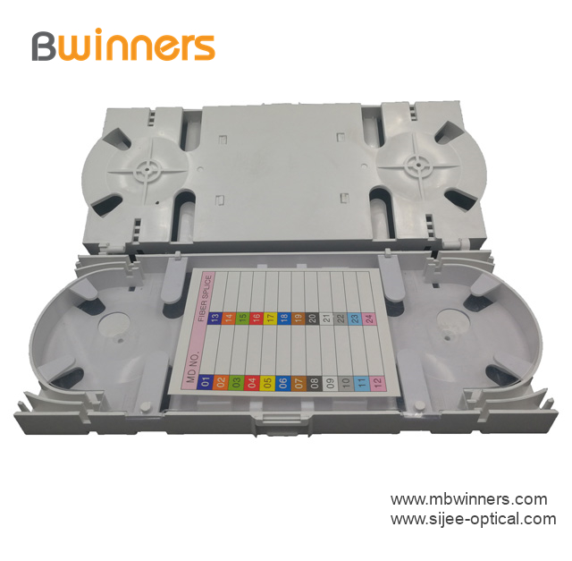
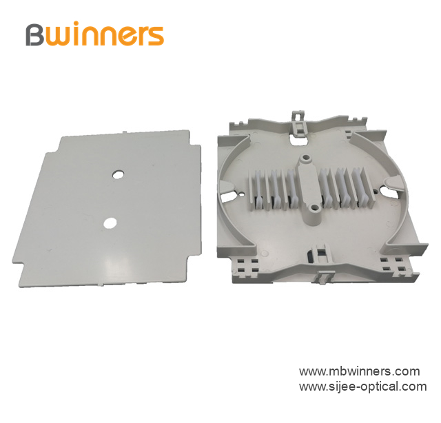
We agree that it is necessary to specify a proper and reasonable low-gray signal starting value specification for the LED display according to the actual display environment brightness. This is in line with the benign collaborative integration of the entire LED display industry chain, and also meets the actual interests of the vast majority of consumers. The development of LED display has experienced the development of monochrome display, gray scale display and full color display, and is currently developing towards high definition with high consistency, high gray level and high display density. People always expect the perfection of things, LED screen is no exception, in various aspects people continue to improve the technology, improve performance, so that the LED screen to achieve vivid and realistic display. In actual engineering, various parameters of the LED display, such as grayscale and field frequency, although the values ​​adopted by various companies according to different understandings are different, in fact, whether it is a monochrome screen, a two-color screen, a gray screen Or full-color screen, the selection of various design parameters of LED display is not arbitrary, but there are many restrictions. In the design, repeated selection of parameters still have certain design principles to be observed. In the past ten years of LED display technology development, new devices and new technologies have been continuously adopted, manufacturing costs have been gradually reduced, and the division of labor has been continuously refined. However, a large number of applications have also exposed some defects in LED display technology. In general, the technology is not yet mature. The standard has not been fully established. The national standard for LED display industry (SJ/T11281-2007) has already standardized the relevant technical parameters of display products, but it involves display components such as diode LEDs, power supply systems, control systems and structural components for display illumination. On the other hand, more in-depth standardization research and related normative documents are needed. The viewing environment for outdoor or semi-outdoor LED displays has a high brightness, so the signal brightness must be different from the background brightness (ratio). In general, if the text can be 2:1, if there is a difference in the image, experience 10:1 is the minimum allowed, 20:1 is the standard, and hope is above 40:1. The definition of brightness level in the industry test standard is: indoor environment illumination is 100 × (1 + 10%) LX and outdoor environment illumination is 10000 (1 + 10%) LX, the brightness level reaches 20 or higher. Into the C level (the highest level). "LED display low gray signal starting condition" combined with the actual display environment conditions of the LED display, through the study of the driving conditions of the system, power supply, constant current drive, LED opening parameters, etc., as soon as possible to develop a more reasonable chip, The industry inspection standards for systems, power supplies and LED tubes are expected by the entire industry. Under the trend that LED display manufacturers are gradually pursuing high-gray display of LED displays, it is more urgent to discuss the rationality of low-gray conditions for LED displays. The module drive circuit of the LED display generally includes two circuit topologies, static and dynamic, as shown in Figure 1 and Figure 2. After the image (video) signal is serially encoded by the controller, the serial image data (OE, LAT, SDI, SCLK, and SDO) are transmitted and distributed by the constant current IC cascade, and the constant current IC will be serialized. The image signal is serially converted and converted to drive each LED tube in the LED dot matrix; under the normal condition of the positive supply voltage of the LED tube, the output channel of the constant current driving IC is turned on by the effective image bit driving signal and Turn off, so as to achieve the function of driving the LED to light and extinguish; the current of the constant current driving IC is adjusted by the external resistor REF, and the current magnitude is adjusted by changing the value of REF. From the circuit diagrams of Figure 1 and Figure 2, the direct factors affecting LED lighting include: image (video) bit drive signal, LED tube, dot matrix module power supply, constant current IC signal drive characteristics, LED The circuit design of the dot matrix module and other factors. This article describes the low-gray conditions of LED display from the technical characteristics of these aspects. Under the same conditions, the dynamic scanning circuit requires a shorter scanning time and a lower gray grading condition because of the dynamic and static scanning circuits. Therefore, the dynamic driving circuit of the 1/4 scan is taken as an example. discuss. Figure 1, LED display static constant current drive circuit diagram Figure 2 LED display dynamic 1/4 sweep constant current drive circuit diagram FTTH Fiber Optic Splice Tray is designed to provide a place to store the fiber cables and splices and prevent them from becoming damaged or being misplaced. It is also called a splice enclosure or splice organizer. This device does not contain any technical functions, and the design is simple. Also, Fiber Optic Tray has a very low price for people to afford. However, the importance of fiber splice tray for protecting fibers is significant. And the skills needed for using a fiber splice tray is not as simple as you think.
Fiber splice trays are usually placed in the middle of a route where cables are required to be joined or at the termination and patch panel points at the end of the cable runs. Also, splices can be placed in a splice tray which is then placed inside a splice closure for OSP (outside plant) installations or a patch panel box for premises applications. As for indoor application, fiber splice trays are often integrated into patch panels to provide for connections to the fibers.
FTTH Fiber Optic Splice Tray Fiber Optic Tray,Fusion Splice Box,Fiber Optic Cable Tray,Splice Tray Optic Fiber Sijee Optical Communication Technology Co.,Ltd , https://www.sijee-optical.com
Made by industrial high-quality ABS plastic, Fiber Optic Cable Tray is provided to place the fiber splice points and pre-terminated for fiber connectivity. The splice tray expands fiber splice capabilities as well as provides the splicing location for fiber optic cables. It can be put into the fiber distribution frame, fiber splice closure, optic terminal box, etc. Sijee offers different shapes of fiber splice tray with or without termination function. Fiber Optic Tray, Fusion Splice Box, Fiber Optic Cable Tray, Splice Tray Optic Fiber are available.
Applications:


