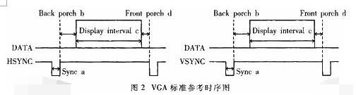
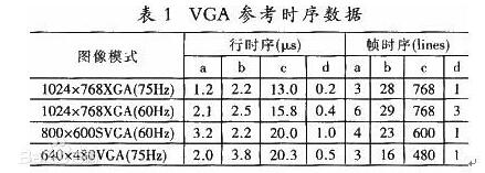
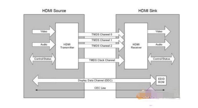
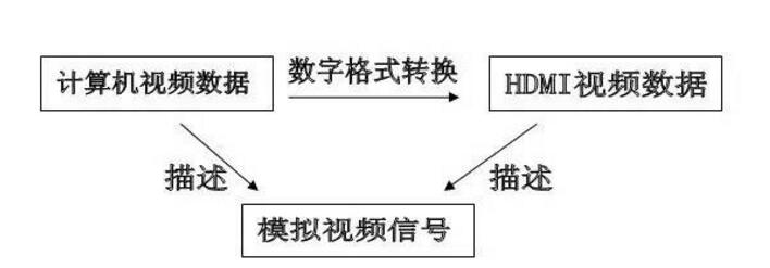
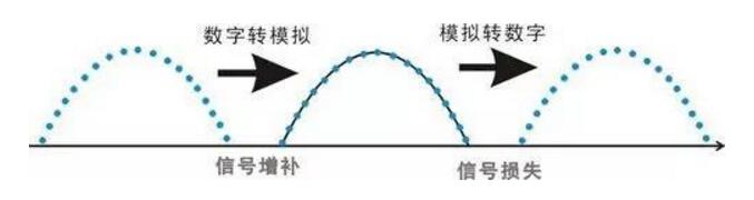
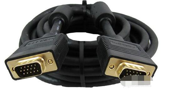
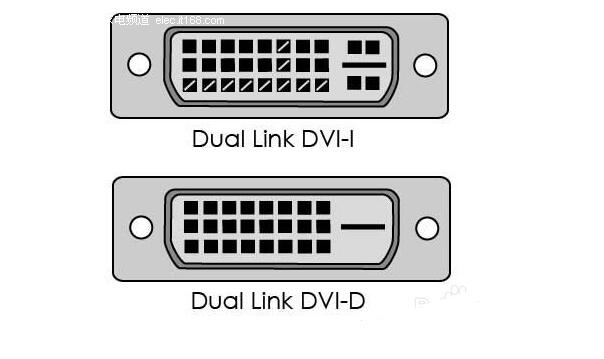
VGA (Video Graphics Array) is a video transmission standard that IBM introduced with the PS/2 machine in 1987. It has the advantages of high resolution, fast display speed, and rich colors. It has been widely used in the color display field. Does not support hot swap, does not support audio transmission. Display and timing: The universal VGA display card system is mainly composed of three parts: a control circuit, a display buffer, and a basic BIOS (Basic Input Output System) program. Control circuit shown in Figure 1. The control circuit mainly completes the functions of timing generation, display buffer data operation, master clock selection and D/A (Digital to Analog converts digital signals into analog signals) functions; the display buffer provides display data cache space; the video BIOS is used as a control program. Cured on the display card's ROM (read-only memory, read-only memory). VGA timing analysis: Through the analysis of the basic working principle of the VGA display card, we can see that to achieve VGA display we must solve the data source, data storage, timing implementation and other issues, the key is how to achieve VGA timing. The standard reference display timing of VGA is shown in Figure 2. Both the row timing and the frame timing need to generate four parts: a sync pulse, a display porch b, a display interval c, and a front porch d. The timing parameters of several common modes are shown in Table 1. VGA timing implementation: First, determine the master clock frequency based on the refresh rate, and then calculate the total number of line cycles from the master clock frequency and image resolution. Then, use the main count pulse source for each of the a, b, c, and d timing segments given in Table 1. The frequency is converted into the number of clock cycles. Using counters and RS flip-flops in the CPLD, based on the calculated number of clock cycles in each timing segment, generate pulse signals of different widths and cycles, and then use their logical combination to construct a, b, c, d in FIG. 2 . Each time segment and D/A converter blank signal BLANK and synchronization signal SYNC. SRAM address: The master clock counts the pulse signal as a pixel, and simultaneously supplies the read signal and the D/A conversion clock of the memory SRAM. The output of the counter driven by the master clock serves as the lower address of the read SRAM. The line synchronization signal serves as a line number count pulse signal, and the output terminal of the counter it drives serves as the upper address of the read SRAM. Due to the use of two SRAMs, the highest bit address is used as the chip select for the SRAM. Because there is a certain time delay when the signal passes through the CPLD internal logic device, when the CPLD generates an address and reads the signal to read data, the read signal, the address signal, and the data signal cannot satisfy the timing requirements of the SRAM read data. The hardware circuit can be used to perform certain timing adjustments on the read signal so that the signals can meet the timing requirements for reading SRAM and input data for the DAC. data: If the VGA displays a true color BMP image, the R, G, and B components each have 8 bits, that is, 24 bits represent one pixel value, and in many cases, 32 bits are used to represent a pixel value. In order to save memory space, high-color images can be used. That is, each pixel value is represented by 16 bits. The R, G, and B components use 5 bits, 6 bits, and 5 bits, respectively, which is half the amount of data in a true color image. , At the same time, it can meet the display effect. DVI is based on TMDS (TransitionMinimizedDifferentialSignaling), the minimum differential signal conversion technology to transmit digital signals, TMDS uses advanced encoding algorithms to encode 8bit data (R, G, B in each channel of the primary color signal) into 10bit data (including lines Field synchronization information, clock information, data DE, error correction, etc.) After DC balancing, differential signals are used to transmit data. Compared with LVDS and TTL, it has better electromagnetic compatibility performance and can be realized with a low-cost dedicated cable. Distance, high quality digital signal transmission. TMDS technology connection transmission structure shown in Figure 1. The Digital Video Interface (DVI) is an international open interface standard that has a wide range of applications on PCs, DVDs, HDTVs, high-definition projectors, and other devices. In DVI principle, the RGB digital signal to be displayed is combined with the HV signal, and each pixel is digitally encoded according to the minimum non-return-to-zero encoding method for 10 bits of digital signals and converted into series. The encoded RG.B digital serial Four signals, such as the code stream and the pixel clock, are transmitted in a balanced manner. Each channel has a code flow rate 10 times that of the original pixel. For example, the resolution is 1024 x 768 x 70, and the stream clock is 70 Mbps x 10, This is equivalent to 0.7Gbps. The typical DVI 1.0 bitstream is between 0.24Gbps and 1.65Gbps. HDMI is the abbreviation of (High Definition Multimedia Interface), which means high-definition multimedia interface. It is a digital video/audio interface technology. It is a dedicated digital interface suitable for image transmission. It can simultaneously transmit audio and video signals with the highest data transmission speed. It is 48Gbps (2.1 version). At the same time, it is not necessary to perform digital/analog or analog/digital conversion before signal transmission. HDMI can be combined with Wideband Digital Content Protection (HDCP) to prevent unauthorized copying of copyrighted audio and video content. This picture shows the architecture of the HDMI interface. From the source on the left, you can see that the source of the HDMI interface can be any device that supports HDMI output, and the access terminal can also be any device that has an HDMI input interface. Whether they are audio devices, video devices or control devices, the HDMI interface can be applied. The data signal in the HDMI interface uses the TMDS minimized transmission differential signaling protocol. This data transmission protocol has been widely used on the DVI interface. The data signal on the HDMI interface also follows this protocol. This protocol converts standard 8-bit data to 10-bit signals and uses differential transmission during conversion. Differential transmission of this technology has also been widely used in Gigabit Ethernet data transmission. Three TMDS data channels can be used to transmit audio and video data in the HDMI interface. The video information is converted to continuous 24-bit pixel data during transmission, and 10 bits of data can be transmitted per clock cycle. The pixel clock cycle transmission ratio is approximately between 25MHz and 165MHz. In general, the pixel clock transmission ratio of the standard NTSC 480i interlaced signal is approximately 13.5 MHz. If the ratio of the transmitted signal is less than 25MHz, HDMI will use automatic looping to fill in the bitrate and increase the bitrate of the signal to 25MHz. The HDMI interface can transmit a maximum of 165 Mpixel data per second. This data throughput capability is quite amazing. In the next period of time enough to cope with high bit rate, high data flow home appliances signal transmission tasks. The highest standard for HDTV is 1080p, and its resolution per screen is 1920X1080. If 60 frames of image (1080p@60) are transmitted per second, the final pixel clock transmission rate is 124.4MHz. From this point of view, the HDMI interface can fully meet the needs of today's consumer electronics products. The three are not equivalent, HDMI and VGA are signal transmission methods, and HD is a video resolution. HDMI supports HD, and VGA also supports it. HDMI currently supports up to 1920 * 1080P HD format, VGA support from 640 * 480 all the way up to 2560 * 1600 of various resolutions, but VGA is very vulnerable to other signal interference, so the high-definition resolution is a little virtual, in order to avoid the picture Interference, below 1920*1080P resolution, VGA interface can be used. The bandwidth of HDMI is the bandwidth of digital signals, and VGA is the bandwidth of analog signals. This is a transmission method of two different technologies. If you want to compare, you can compare the same resolution, such as high-definition, HDMI requires 2.2GHz bandwidth, and VGA only requires 172MHz bandwidth. However, the high bandwidth does not mean that HDMI transmits more video signals. This is just because of the different transmission technologies. Although HDMI does not require digital analog conversion, it still has to undergo digital to digital conversion. No matter what kind of conversion process it is, what is converted into it is ultimately a description of the analog electrical signal. Their relationship is as follows: The signal described by the digital signal is composed of one point, which is incoherent in the change of the signal, and the change of the analog signal is a continuous curve, so the analog signal gives a better sense of reality. When the digital signal is converted to an analog signal, it comes out one by one (the sample point of the digital signal), and the undescribed part is automatically generated by the conversion program (similar to the anti-aliasing technology with 3D) to form a continuous Analog signal waveform. When an analog signal is converted to a digital signal, the continuous analog signal is converted into a digital signal describing one point, and the signal becomes incomplete. From this point of view, the conversion of digital signals to analog signals is enhanced rather than loss, and there is a loss of analog signals to digital signals. In the VGA transmission process, the signal loss from the VGA to LVDS-driven LCD panel is negligible, because in the case of the same digital sampling rate at the front and rear ends, these lost signals are (when the digital signal is converted to an analog signal). The part that is filled in is not the loss of the original signal of the digital signal source. Pictured: 1. VGA connector: The video interface with 15 pins is mainly used for old computer output. The VGA output and transfer are analog signals. Everyone knows that computer graphics produce digital signals, and monitors use digital signals. So the video interface using VGA is equivalent to going through a digital-to-analog conversion and an analog-to-digital conversion. Loss of signal, the display is more vague. 2, DVI interface: DVI interface has two standards, 25-pin and 29-pin, as shown below. Intuitively, there is no difference between the two interfaces. The DVI interface transmits digital signals and can transmit large-resolution video signals. No conversion occurs when the DVI is connected to the computer graphics card and monitor, so the signal is not lost. 3, HDMI interface: HDMI interface is also a digital signal transmission, so in the video quality and DVI interface transmission to achieve the same effect. The HDMI interface can also transmit audio signals. If the monitor has a sound in addition to the display function, the HDMI interface can simultaneously transmit the computer video and audio signals to the monitor. HDMI has three interfaces. Mainly take into account the needs of the equipment. If the digital camera is small and requires a small interface, use microHDMI. The three types of interfaces differ only in size and function. 1. VGA and DVI mutual conversion: conversion of analog signals and digital signals, loss of video signals, and distortion. It is best not to change this way. 2. DVI and HDMI transfer: Both are digital signals and conversion does not happen. Can be converted. However, audio signals are automatically discarded when converting from HDMI to DVI CCTV Microphone,Microphone For Security Camera,Cctv Audio Microphone,CCTV Audio Picker Chinasky Electronics Co., Ltd. , https://www.cctv-products.com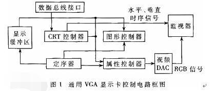
About the three misunderstandings of VGA, DVI, and HDMI
First, VGA principle