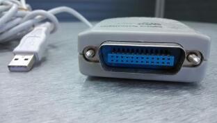
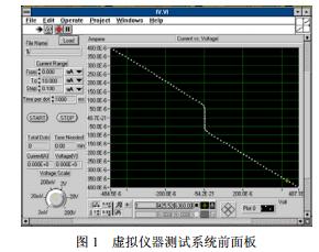
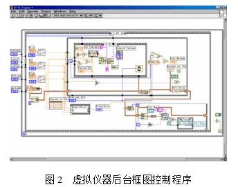
The GPIB universal interface bus is a device and computer connected bus. Most desktop instruments are connected to computers via GPIB lines and GPIB interfaces. This article introduces the GPIB bus interface technology for virtual instruments. The computer controls the current source and voltage meter with the GPIB bus interface through the GPIB interface card, forms the I-V curve virtual instrument test system. In the Labview environment, the design of the virtual instrument front panel and background block diagram program is completed, and the virtual instrument testing task is completed together with the hardware system. Through the GPIB interface technology, various kinds of instruments and equipments produced by different manufacturers can be conveniently combined with a computer to build an automatic test system. In the past, to communicate between the instrument and the computer, the user had to spend a lot of time and effort on familiarity with the programming of various instruments. In recent years, the rapid development of virtual instrument technology has provided a good development platform and instrument driver for the formation of the GPIB automatic test system. The use of a virtual instrument software development platform fundamentally eliminates the complexity of instrument programming, allowing users to focus on the use of the instrument rather than the instrument's programming. Because the computer uses a bus with a completely different standard from the GPIB bus, in order for the computer to function as a GPIB system controller, an interface card connected to the GPIB bus must be inserted into the expansion slot of the computer. There are two methods for the control of the GPIB interface card by the virtual instrument software Labview. One is to use the GPIB and GPIB488.2 function templates or VISA library provided in Labview. This method can only be used on NI's own GPIB interface board or The GPIB488 interface board of the VISA library is controlled and its price is relatively expensive. Another method is to use the call library function (CallLibraryFunction) provided by Labview itself to implement the control of the GPIB interface card by calling the GPIBDLL dynamic link library. Relatively speaking, this method is cheap, and more versatile, and other similar hardware devices, as long as it can provide a dynamic link library in the Windows environment, but also know its function prototype, can be applied in Labview. This article uses the AX5488 interface board which is widely used and relatively inexpensive, and implements GPIB interface card control through Labview's call to its GPIBDLL. Based on this, through the control of the current source and voltage meter with GPIB interface, a virtual instrument test system for I-V curves is constructed. According to the principle of the virtual instrument system based on GPIB bus, we have established a virtual instrument test system for I-V curves. The computer automatically tests and controls the Keithley 220 current source and the Keithley 2182 nanovoltmeter through a GPIB interface card. Four-lead measurement is used for measurement. Two current leads are connected to a constant current source. Two voltage leads are connected to a voltmeter to measure the voltage of the sample. Because of the high input impedance of the voltage measurement circuit, the current drawn is extremely small. Avoid the effects of lead and contact resistance on the measurement. To complete the test function of the virtual instrument, the design of the software is the key. Labview-based virtual instrument test software design includes front panel design and background graphic control program design. The front panel is a graphical user interface that simulates real instruments and consists of controls, indicators, and modifiers. Users can use a variety of icons, such as buttons, switches, real-time trend graphs, and postmortem recorders, to set input values ​​and observe output. Figure 1 shows the front panel of the I-V curve virtual instrument we built. It mainly includes: (1) Start button START: Click to start the test; (2) Stop button STOP: Click to stop the test; (3) Voltmeter range selection switch: Select voltmeter range according to test accuracy requirements; (4) current source output current setting: including starting current, end point current, and step-by-step value; (5) Voltage and current value display: display current set current value and test voltage value; (6) Real-time I~V curve: Real-time trend shows I~V curve, and can be adjusted in real time; (7) Test result save file setting: set the path and file name of the test result saved as a text file; (8) Other auxiliary instructions: including the total number of test points, the time required for each test, and the remaining test time. The back panel of the front panel corresponds to a set of block diagram programs, which are written in graphical languages ​​and consist of nodes and data connections. Figure 2 shows the background block diagram control program for the I~V virtual instrument test, including the function call module, waveform display module, parameter measurement module, data storage and playback module, and test control structure module for the GPIB DLL. Only parts of the figure can be displayed. Block diagram program. The Labview program controls the test instrument through the GPIB bus. It is actually implemented by calling the GPIB DLL of the GPIB card through the call library function (CallLibraryFunction) provided by Labview itself. Before calling the DLL, you should understand the following information: (1) The path where GPIBDLL is stored in the computer; (2) The function returns the data type: Void, Numeric, or String; (3) The data type passed to the function form parameter and the passing procedure of the parameter; (4) DLL usage call procedure. Two calls can be made using C and Stdcall (the default), and the Win32 API uses the default Stdcall procedure. All background control program modules include corresponding functions, structures, code interfaces, and subroutines. Nodes, nodes, and front panel objects communicate data through data ports and data connections. After the design of each block diagram program control module is completed, these modules are organically combined in the main program according to a certain logical relationship to form a V-curve virtual instrument oscilloscope, which forms a complete virtual instrument together with the hardware of the system. The test system fully embodies the idea that "software is the instrument". This article is based on the GPIB bus technology, the computer controls the current source and voltage table with GPIB bus interface through the GPIB interface card, has established a set of I~V curve virtual instrument test system. In the Labview environment, the design of the virtual instrument front panel and background block diagram program is completed. It completes the virtual instrument testing task together with the hardware system. This is also the basic principle of the virtual instrument system based on the GPIB bus. High Speed Blender,Ipl Laser Hair Removal,Diy Laser Hair Removal,Best Ipl Hair Removal,Epilator Ipl SHENZHEN CHONDEKUAI TECHNOLOGY CO.LTD , http://www.siheyidz.com